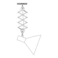
The Modern Pantograph is a device designed for suspending studio lights, allowing for flexible positioning and movement. It is essentially a scissor-like mechanism that can extend and retract, providing vertical adjustment for lighting fixtures.
Function Description:
The primary function of the Modern Pantograph is to provide a versatile and adjustable mounting solution for studio lights. It allows users to raise, lower, and position lights precisely within a studio environment, ensuring optimal lighting for various photographic or videographic setups. The pantograph's design, with its interconnected arms, enables smooth and controlled movement, making it easier to achieve desired lighting angles and heights without the need for cumbersome stands on the floor. The device is typically mounted on a sliding track, which further enhances its flexibility by allowing horizontal movement across the studio.
Important Technical Specifications:
The pantograph consists of several key components that work in conjunction to achieve its function:
- Track (1): The horizontal rail on which the pantograph moves.
- Track roller (2), Track roller socket (3), Track roller socket bolt (4): These components facilitate the smooth horizontal movement of the pantograph along the track.
- Tension wire lock (5), Tension wire stud (6), Tension wire (7): The tension wire system is crucial for counterbalancing the weight of the attached light and allowing for easy vertical adjustment. The lock and stud secure the tension wire.
- Body cage (8), Body stud (9), Body spacer (10): These form the main structure of the pantograph's body.
- Light wire hook (11): Used for managing the light's power cable along the pantograph.
- Spring case (12): Houses the internal spring mechanism that provides the counterbalancing force for the tension wire.
- Locking gear (13), Locking lever (14): These components are used to secure the pantograph at a desired vertical position.
- Light stud (15): The mounting point for the studio light, typically a standard 5/8 inch (or 19mm) stud.
Usage Features:
Installing/Removing Track Roller:
- Installation: Insert the track roller stud into the upper part of the pantograph body. Place the track roller socket over the track roller stud and secure it with the track roller socket bolt. Ensure the track roller can rotate freely 360 degrees without coming out of the socket.
- Removal: Open the track roller socket bolt and pull out the track roller.
Mounting Light Wire:
- The light wire should be threaded along the pantograph's arms using the track wire hooks.
- Start by sliding the track wire hooks into the lower track of the sliding track.
- For every 2 feet of sliding track, use 3 or 4 track wire hooks.
- Slide the light wire hook from one end of the sliding track to the other.
- Attach the light wire to the lower end of the pantograph.
- Keep the wire hooked onto one track wire hook per one arm of the pantograph in a zigzag pattern, ensuring the wire is not stretched when the pantograph is elongated.
- Once the wire reaches the top wire hook on the pantograph, stretch it and pass it one by one from each track wire hook on the sliding track by making a loop of about 1 foot diameter, ensuring the wire is not stretched when the pantograph slides.
Mounting/Unmounting Studio Light:
- Mounting: The pantograph provides a 5/8 inch (or 19mm) standard size light stud. Insert the light stud on the pantograph into the socket on the studio light. Fasten the bolt on the light socket around the light stud to secure it.
- Unmounting: Loosen the bolt on the light socket and pull down the light.
Light Orientation:
- The orientation of the light with respect to the pantograph body cage is very important for smooth functioning.
- Rotate the light along the light stud on the pantograph to achieve the desired orientation, as shown in the provided diagrams (Proper Orientation vs. Improper Orientation).
Increasing/Decreasing Pantograph Spring Tension:
-
Step 1: Opening Tension Wire Lock:
- Unmount the studio light for safety.
- Open the lower track end stop of the sliding track and unmount the pantograph in its shortened form.
- Place the pantograph firmly on the ground with the light stud touching the ground, keeping the pantograph upright.
- Hold the spring case firmly to prevent tension loss when the wire is loosened.
- Open the tension wire stop near the tension wire stud.
- Note: Keep the tension wire firmly stretched around the spring case throughout the process to prevent coiling.
-
Step 2: Increasing/Decreasing Tension:
- Increasing: Once the tension wire lock is removed, loosen the spring case lightly (while still holding it) and pull out approximately 1 foot of tension wire. This stretches the spring and adds tension.
- Decreasing: Unwind 1 turn of the tension wire from around the spring case (while holding it firmly). Loosen the spring case lightly, allowing it to wind itself with the extra length of unwound wire, thereby decreasing tension.
-
Step 3: Winding Extra Round of Tension Wire (for increasing tension):
- Hold the spring case firmly to maintain applied tension.
- While holding, wind an extra round of tension wire around the spring case.
- Ensure the tension wire is firmly stretched.
-
Step 4: Restoring Tension Wire and its Lock:
- Once tension is set, take the end of the wire and pass it through the tension wire stud on the upper part of the pantograph.
- Ensure the spring case is held firmly to prevent unwinding.
- After passing the tension wire through the tension wire stud, restore the tension wire lock.
- Loosen the spring case lightly (while still holding it) to allow it to wind itself with any extra length of tension wire.
- Mount the pantograph on the sliding track and restore the light.
- Press the locking lever and move the pantograph up-down 3-4 times to check the tension.
Handling Pantograph Tension Wire Breakage/Replacement:
-
Step 1: Opening Tension Wire Lock: (Same as above)
-
Step 2: Unwinding/Replacing Tension Wire:
- Once the tension wire lock is removed, unwind the entire tension wire from around the spring case until its end is attached to the spring case.
- If the tension wire is broken, it must be replaced with a new wire.
- Remove the wire completely by passing it through the small hole on the side of the spring case.
- The wire, called 'Rear engine gear inner', is available at local automobile shops.
- Pass the new wire through the small hole on the side of the spring case from where the earlier wire was taken out.
- Note: Care should be taken to ensure the spring case does not turn in a clockwise direction when seen from the side.
-
Step 3: Rewinding Entire Tension Wire Around Spring Case:
- The new tension wire is unwound and attached to the spring case only at its end.
- Start winding around the spring case turn by turn in the anti-clockwise direction when the spring case is seen from the side of the pantograph.
- Note: Keep the tension wire firmly stretched during this process. If it is left loose, it might get coiled, requiring the entire tension wire to be opened and rewound.
-
Step 4: Restoring Tension Wire and its Lock: (Same as above)
Pantograph Usage and Handling Good Practices:
- Follow proper light orientation when mounting lights.
- Keep the pantograph in shortened form when lights are not in use.
- Use the locking lever for shortening the pantograph. If the pantograph is often shortened without lifting the locking lever, the lever may get damaged over a longer period.
- Never pull the pantograph down without pressing the locking lever. If more load is applied without pressing the locking lever, it may deform the pantograph structure and hamper its functionality.
- Ensure that while sliding the pantograph, its body cage should not bend on side-ways. This can deform the structure and hamper functionality.
- While sliding the pantograph on the sliding track, push/pull it from the bottom and center position.
Maintenance Features:
- Clean the pantograph at least 2-3 times a week.