14
5-564
➅ Air Flow Proving Switch
The air flow proving switch is factory installed in the duct furnace
electrical junction box. The air flow proving switch monitors the
pressure differential between the duct furnace and the atmosphere.
The purpose of the air flow proving switch is to cut power to the
gas controls if a positive pressure is not measured by the switch.
This could be caused by a lack of air movement through the heat
exchanger.
NOTE: The air flow proving switch will prevent any heat
exchanger warm-up (the unit should not be equipped with
a time delay relay) because the gas controls can not be
energized until air flow is proven.
Setting the Air Flow Proving Switch
The range of the air flow proving switch is adjustable between 0.17"
to 5.0" W.C.
1. Set the thermostat so that there is a call for heat. This should fire
the burner and the blower should start.
2. Turn the set screw of the pressure switch clockwise until it stops.
This will set the pressure at 5.0" W.C.
3. Turn the screw counter-clockwise until the gas controls light and
then one additional full turn (This is approximately 0.25'' W.C.).
This will allow for dirty filters or any other slight static pressure
increases in the system.
➆ Manual Reset High Limit
The manual reset high limit switch is factory installed in place
of the standard automatic reset high limit switch located in the
duct furnace electrical junction box. In case of a failure of the
blower motor, blockage of the inlet air, etc., the manual reset
switch prevents the unit from cycling on the high limit. If the limit
temperature is exceeded, a service person must inspect the unit for
the cause of the high discharge temperature, take corrective action,
and then reset the switch.
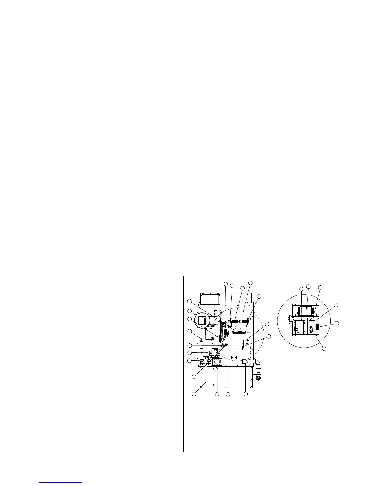
Figure 14.1 - Location of Gas Control Options
Gas Control Options
The unit must be reviewed to determine if any of the listed gas
control options were supplied.
➀ Time Delay Relay
The Time Delay Relay is factory installed in the duct furnace
electrical junction box. The standard duct furnace is provided
for instantaneous fan operation. On a call for heat, the blower is
energized at the same time as the gas controls. The optional time
delay relay allows the gas controls to operate for approximately 30
seconds before the blower starts. This allows the heat exchanger
a warm up period so that the initial delivered air coming out of the
ductwork is not cool. The time delay relay also keeps the motor
running for approximately 30 seconds after the call for heat has
been satisfied to remove the residual heat from the heat exchanger.
➁ Low Gas Pressure Switch
The low gas pressure switch is factory installed in the duct furnace
above the gas train. The switch monitors the gas pressure upstream
of all the gas controls and shuts off the electric supply to the
ignition controller and combination gas valve if low gas pressure is
experienced. This will shut off all gas flow to the burner. The switch
has an automatic reset so that if the gas pressure is interrupted
and then is returned, the switch will automatically allow the unit to
operate when gas conditions are returned to the allowable range
of the pressure switch. The pressure switch range is 2" to 14" W.C.
and should be set to insure that the minimum inlet gas pressure is
available (6" W.C. for natural gas, 11" W.C. for propane gas).
➂ High Gas Pressure Switch
The high gas pressure switch is factory installed in the duct
furnace above the gas train. The switch monitors the gas pressure
downstream of all the gas controls and shuts off the electric supply
to the ignition controller and combination gas valve if high gas
pressure is experienced right before the manifold. This will shut off
all gas flow to the burner. The switch has a manual reset so that if
the gas pressure is too high, a service person must check the unit
to make sure that none of the gas controls have been damaged
by the high gas pressure and then reset the switch to allow the
unit to operate when gas conditions are returned to the allowable
range of the pressure switch. The pressure switch range is 2" to 16"
W.C. and should be set to insure that the maximum manifold gas
pressure is not exceeded (3.5" W.C. for natural gas, 10" W.C. for
propane gas).
➃ Supply Air Fire Stat
The fire stat is factory installed in the duct furnace electrical junction
box with the sensor in the discharge air stream. In case of elevated
temperatures in the supply air, the manual reset switch shuts
down the entire unit. If the limit temperature is exceeded, a service
person must inspect the unit for the cause of the high discharge
temperature, take corrective action, and then reset the switch.
➄ Timed Freeze Protection
The timed freeze protection system is factory installed in the duct
furnace electrical junction box with the sensor (30°-75°F adjustable)
factory installed in discharge air stream. On initial start-up, the
timed delay in the system allows the unit to go through the normal
ignition sequence. The timed delay is an automatic reset switch and
adjustable for 1-10 minutes. In the event that the unit fails to fire
after this period, the discharge air sensor will sense the cold air and
will shut down the entire unit.
OPTIONS
Units with Standard
Control Panel
Units with Premium Control Box
13
48
6
46
6
8
57
9
13
49
2
3
50
5
4
1
10
9
8
12
46
47
55
51
52
12
300
FM
R
LISTED
PRESSURE
OPERATED
SWITCH
504H
ADDISON
IL. U.S.A.
MODEL
RLGP-A
M1
LOW
PRESSURE
50
100
150
200
350
250
mm.
W.C.
2
4
6
8
10
14
IN.
12
300
FM
R
LISTED
PRESSURE
OPERATED
SWITCH
504H
ADDISON
IL. U.S.A.
MODEL
RLGP-A
M1
LOW
PRESSURE
50
100
150
200
350
250
mm.
W.C.
2
4
6
8
10
14
IN.
12
3
456
A1010 Amplifier
89101114
GH
T
PV
MV
LED
TH
PV/MV
GND
TR
SENSE
1. Discharge Thermostat
2. Low Gas Pressure Switch
3. High Gas Pressure Switch
4. Power Exhauster
5. Timed Freeze Protection
6. Ignition Controller
8. Control Relay
9. Time Delay Relay
10. Furnace Low Voltage Terminal Strip
12. Furnace Supply Power Terminal Strip
Note: Wrap around gas train on
premium and electronic
modulation units only.
13. Control Step Down Transformer
46. Electronic Modulating Amplifier
47. Electronic Modulating Gas Valve
48. Air Flow Proving Switch
49. High Limit Switch
50. Supply Air Fire Stat
51. Main Gas Valve
52. Burner Box
55. Differential Pressure Switch
57. Control Terminal Board
 Loading...