5-564
UNIT LOCATION
Location Recommendations
1. When locating the furnace, consider general space and
heating requirements, availability of gas and electrical
supply, and proximity to vent locations.
2. Unit must be installed on the positive pressure side of the
circulating blower.
3. Be sure the structural support at the unit location site is
adequate to support the weight of the unit. For proper
operation the unit must be installed in a level horizontal
position.
4. Do not install units in locations where the flue products
can be drawn into the adjacent building openings such as
windows, fresh air intakes, etc.
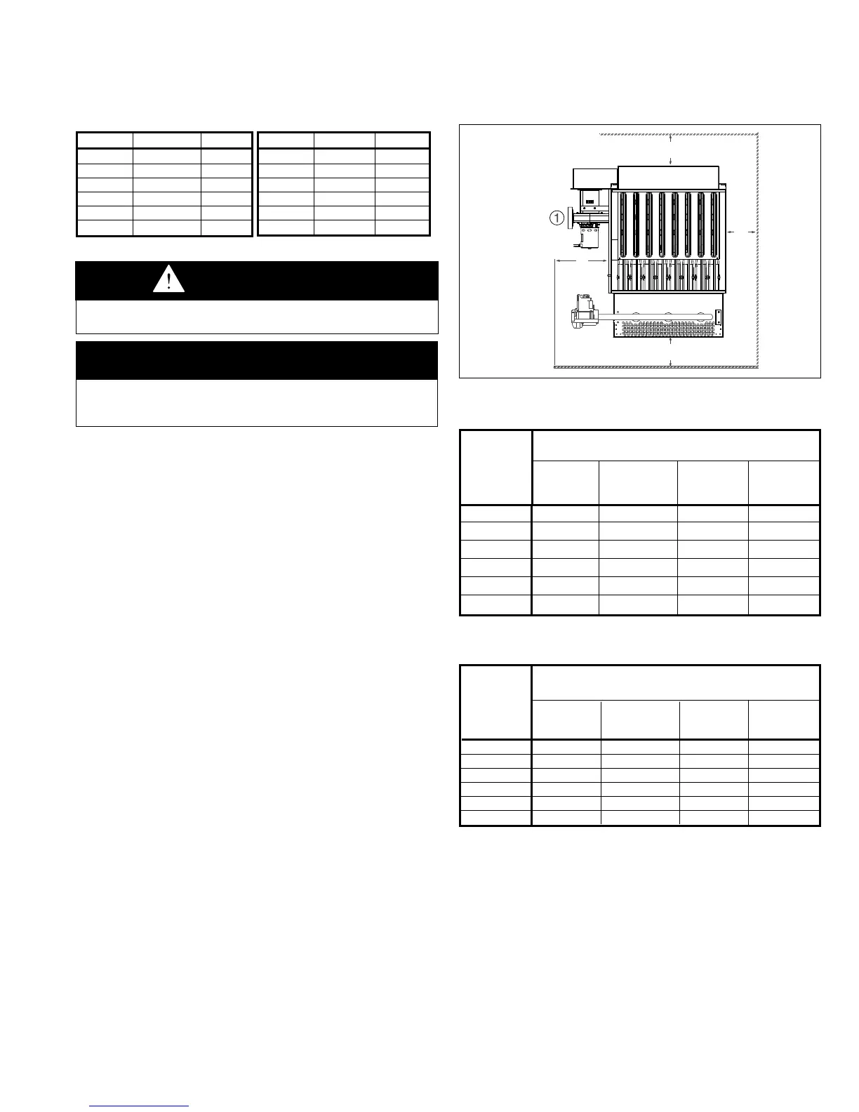
5. Be sure that the minimum clearances to combustible
materials and recommended service clearances are
maintained. Units are designed for installation on non-
combustible surfaces with the minimum clearances shown
in Figure 3.1 and Tables 3.2 and 3.3.
6. Units installed downstream of refrigeration systems, or
exposed to inlet air temperatures of 40°F or less, may
experience condensation, therefore, provisions should
be made for disposal of condensate. Means have been
provided in the bottom pan of the unit to accommodate a
condensate drain line connection flange.
7. When locating units, it is important to consider that the
exhaust vent piping must be connected to the outside
atmosphere.
8. In garages or other sections of aircraft hangars such as
offices and shops which communicate with areas used for
servicing or storage, keep the bottom of the unit at least 7”
above the floor. In public garages, the unit must be installed
in accordance with the Standard for Parking Structures
NFPA #88A and the Standard for Repair Garages NFPA
#88B. In Canada, installation of unit heaters in airplane
hangars must be in accordance with the requirements of
the enforcing authority, and in public garages in accordance
with the current CAN/CGA-B149 codes.
9. Do not install units in locations where gas ignition system is
exposed to water spray, rain, or dripping water.
33
SI (METRIC) CONVERSION FACTORS / UNIT LOCATION
DANGER
Appliances must not be installed where they may be exposed
to a potentially explosive or flammable atmosphere.
SI (METRIC) CONVERSION FACTORS
Table 3.1
Recommended
Service
Clearance
Model Access Non-Access Top Bottom
Size Side Side (C) (D)
(A) (B)
75 18" 6" 10" 0"
100/125 20" 6" 10" 0"
150/175 25" 6" 10" 0"
200/225 27" 6" 10" 0"
250/300 30" 6" 10" 0"
350/400 41" 6" 10" 0"
IMPORTANT
To prevent premature heat exchanger failure, do not locate
ANY gas-fired appliances in areas where corrosive vapors (i.e.
chlorinated, halogenated or acid) are present in the atmosphere.
C
B
A
D"
Access
Slide
To Convert Multiply By To Obtain
"W.C. 0.24 kPa
psig 6.893 kPa
°F (°F-32) x 0.555 °C
inches 25.4 mm
feet 0.305 meters
CFM 0.028 m
3
/min
To Convert Multiply By To Obtain
CFH 1.699 m
3
/min
Btu/ft
3
0.0374 mJ/m
3
pound 0.453 kg
Btu/hr 0.000293 kW/hr
gallons 3.785 liters
psig 27.7 "W.C.
Clearance to
Combustible Materials
Model Access
Non-Access
Top Bottom
Size Side Side (C) (D)
(A) (B)
75 12" 1" 3" 2"
100/125 12" 1" 3" 2"
150/175 12" 1" 3" 2"
200/225 12" 2" 3" 2"
250/300 12" 2" 3" 2"
350/400 12" 2" 3" 2"
Figure 3.1 - Combustible Material and Service
Clearances
Combustion Air Requirements
Units installed in tightly sealed buildings or confined spaces
must be provided with two permanent openings, one near
the top of the confined space and one near the bottom. Each
opening should have a free area of not less than one square
inch per 1,000 BTU per hour of the total input rating off all
units in the enclosure, freely communicating with interior areas
having, in turn adequate infiltration from the outside.
For further details on supplying combustion air to a confined
(tightly sealed) space or unconfined space, see the National
Fuel Gas Code ANSI Z223.1 of CAN/CGA B149.1 or .2
Installation Code, latest edition.
➀ A 3'' minimum clearance to combustible material is required from the vent collar.
Table 3.2 - Combustible Material Clearances
Table 3.3 - Service Clearances