EasyManua.ls Logo

Moeller P7 Series User Manual

Moeller P7 Series
10 pages
To Next Page IconTo Next Page
Page #1 background imageLoading...
Page #1 background image
1/9
f 60
90°
90°
90°
90°
f 18
P7(4)-...(-M8) NZM7(4)-...N(S, H)(-M, -G)
NZM7(4)-...(-M8) NZM7(4)-...N(S, H)(-M, -G)-M8
NZM7(4)-...-NA(-M8) NZM7(A)-...N(S)-NA(-M8)
10/99 AWA 123-1337
Montageanweisung
Installation Instructions
Notice d’installation
Istruzioni per il montaggio
Instrucciones de montaje
Инcтpyкция пo мoнтaжy
f 80
5 mm
o 3 mm
Z 2
2 X KA...-NZM7(4)
(nur/only/seulement/soltanto/sólo/ : NZM7(4)-...-M8)
NZM7(4)-...N(S,H)
Electric current! Danger to life!
Only skilled or instructed persons may carry out the
following operations.
Tension électrique dangereuse !
Seules les personnes qualifiées et averties doivent
exécuter les travaux ci-après.
Tensione elettrica: Pericolo di morte!
Solo persone abilitate e qualificate possono eseguire
le operazioni di seguito riportate.
¡Corriente eléctrica! ¡Peligro de muerte!
El trabajo a continuación descrito debe ser realizado
por personas cualificadas y advertidas.
Элeктpичecкий тoк! Oпacнo для жизни!
Toлькo cпeциaлиcты или пpoинcтpyктиpoвaнныe
лицa мoгyт выпoлнять cлeдyющиe oпepaции.
Lebensgefahr durch elektrischen Strom!
Nur Elektrofachkräfte und elektrotechnisch
unterwiesene Personen dürfen die im Folgen-
den beschriebenen Arbeiten ausführen.
Question and Answer IconNeed help?

Do you have a question about the Moeller P7 Series and is the answer not in the manual?

Moeller P7 Series Specifications

General IconGeneral
Trip Unit TypeThermal-magnetic
MountingDIN rail
Protection ClassIP20
Poles1P, 2P, 3P, 4P
StandardsIEC/EN 60947-2
Operating Temperature-25 to +70 °C

Summary

General Safety and Product Introduction

Electrical Safety Warnings

Crucial safety instructions regarding danger to life from electrical current for skilled personnel.

Product Model Identification

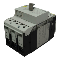
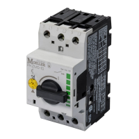
Lists various NZM7 and P7 model series for installation.

Required Tools and Dimensions

Highlights essential tools like screwdrivers and specific dimensions for installation.

Initial Mounting and Wiring Connections

Wire Cross-Section and Length Guidelines

Specifies wire cross-sections (S, X) for 160A and 250A applications.

Torque Specifications for Connections

Provides torque values for electrical connections based on wire gauge.

Mounting Hole and Wire Size Limitations

Details mounting hole configurations and maximum wire sizes.

Assembly Steps and Terminal Shroud Usage

Component Insertion and Securing

Illustrates steps for inserting components and securing covers with screws.

Mandatory Cable Lug Shrouds for Screw Terminals

Emphasizes using specific shrouds (KA...-NZM7(4)) with screw terminals.

Screw Specifications for Pole Configurations

Lists screw types and quantities for 3-pole and 4-pole units.

Further Assembly and Phase Barrier Installation

Accessory Attachment and Securing

Details attaching components to the main unit with specified torque.

Phase Barrier Installation

Instructions for inserting phase barriers into the breaker unit.

Circuit Breaker Setting and Adjustment

Adjusting Rated Operational Current (Iu)

Guide to setting the rated operational current (Iu) using the adjustment dial.

Setting Short-Time Delayed Overcurrent Release (Irm)

Instructions for adjusting the short-time delayed overcurrent release (Irm).

Adjustment Range Limitations

Warning against turning the adjustment dial beyond the maximum setting.

Functional Testing Procedures

Test 1: Basic Operation Check

Procedure to test the ON/OFF switching functionality of the breaker.

Test 2: Trip Mechanism Verification

Demonstrates how to trigger a trip and reset the breaker.

Accessory Integration and Connection

Connecting EK10/EK01 Accessories

Guides connection of EK10/EK01 accessories with RHI and NHI components.

Wire Preparation for Accessory Terminals

Specifies wire gauge and length for connecting to accessory terminals.

Device Marking and Dismantling

Permanent Marking of Device

Instructions for marking the breaker with a water-proof felt pen.

Dismantling Procedure

Step-by-step guide on how to remove the circuit breaker from its mounting.

Mounting Dimensions and Hardware

P7/NZM7 Mounting Hole Layout

Detailed dimensions and hole patterns for mounting P7 and NZM7 series breakers.

Recommended Mounting Hardware

Specifies screw size and torque for secure breaker mounting.

Product Discontinuation and Successor Information

Discontinued Product Notice

Alerts users that the product series is discontinued and no longer available.

Order Successor Product NZM1-4

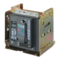
Recommends ordering the updated NZM1, -2, -3, -4 series as a replacement.

Related product manuals