Do you have a question about the Moeller IZM1 Series and is the answer not in the manual?
Displays various symbols used in the manual and their meanings.
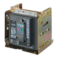
Illustrates the main components of the circuit-breaker with numbered labels.
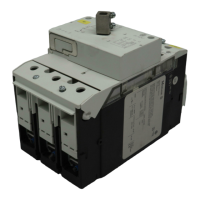
Shows a diagram of the withdrawable unit with its components labeled.
Details the circuit-breaker equipment label with terminal designations and functions.
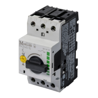
Identifies different types of control units (IZM...-A..., IZM...-U..., IZM...-V..., IZM...-D...).
Defines a "qualified person" and lists the required qualifications for working on the device.
Provides instructions and precautions for lifting the circuit-breaker and withdrawable unit by crane.
General information on installation, safety, and mounting positions.
Instructions for securely mounting the circuit-breaker on a horizontal surface.
Guide for installing the circuit-breaker vertically using appropriate mounting brackets.
Specifies safety clearances required between the circuit-breaker and live/earthed parts.
Details requirements and regulations for operating circuit-breakers in IT systems.
Details horizontal and flange connection methods for circuit-breakers and withdrawable units.
Explains front connection options for fixed-mounted and withdrawable circuit-breakers.
Details vertical connection methods for fixed-mounted and withdrawable circuit-breakers.
Lists part numbers for connecting bars for both fixed-mounted and withdrawable units.
Details arrangement and connection of plug connectors and control circuit plugs for auxiliary circuits.
Explains the retrofitting and use of sliding contact modules for auxiliary connections.
Details the assembly process for control circuit connections and optional accessories.
Shows how to connect the protective conductor for both fixed-mounted and withdrawable circuit-breakers.
Details the process of converting a fixed-mounted circuit-breaker to a withdrawable type, including kit part numbers.
| Brand | Moeller |
|---|---|
| Model | IZM1 Series |
| Category | Circuit breakers |
| Language | English |