08/07 AWB1230-1407D I
Contents
0 About this manual 0 - 1
1 Construction 1 - 1
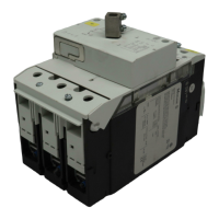
Circuit-breaker 1 - 1
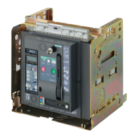
Withdrawable unit 1 - 2
2Labels 2 - 1
Circuit-breaker equipment label 2 - 1
Circuit-breaker label 2 - 1
Identification of the control unit 2 - 2
Rating plug label 2 - 3
Withdrawable unit label 2 - 3
3 Standards and regulations 3 - 1
4 Transport 4 - 1
5 Mounting 5 - 1
Installation 5 - 1
– Mounting position 5 - 1
– Mounting on horizontal surface 5 - 1
– Mounting on a vertical surface with mounting brackets 5 - 2
Safety clearances 5 - 4
– Use in IT systems 5 - 5
Connecting bars 5 - 7
– Horizontal connection 5 - 7
– Flange connection 5 - 7
– Front connection 5 - 8
– Vertical connection 5 - 10
Connection of main conductors 5 - 15
Auxiliary conductor connection 5 - 16
– Plug connector 5 - 16
– Sliding contact module 5 - 17
– Control circuit plug 5 - 17
Wiring on withdrawable unit 5 - 19
– Assembly with control circuit connections 5 - 19
– Order numbers 5 - 19
Connection of protective conductor 5 - 21
Changeover of fixed mounting circuit-breaker
into withdrawable circuit-breaker 5 - 21
Conversion 5 - 22
6 Commissioning 6 - 1
Preparation of withdrawable circuit-breaker 6 - 1
– Inserting the circuit-breaker in withdrawable unit 6 - 1
– Position of the circuit-breaker in the withdrawable unit 6 - 2
– Release racking handle/withdraw racking handle 6 - 3
– Circuit-breaker to connected (CONNECT) position 6 - 3
– Insert racking handle 6 - 3
Charging the spring 6 - 4
Checklist for commissioning 6 - 4
Closing 6 - 5
Switch off 6 - 5
Tripping by overcurrent release 6 - 6
Re-starting a tripped circuit-breaker 6 - 7
Switching off and discharging the storage spring 6 - 8
Troubleshooting 6 - 9
7 Frame sizes, dimension drawings 7 - 1
Overview external dimensions 7 - 1
IZM(IN)...1-..., fixed-mounting, 3- and 4-pole 7 - 2
IZM(IN)...1-..., withdrawable, 3- and 4-pole 7 - 4
IZM(IN)...2-..., fixed-mounting, 3 and 4 pole 7 - 6
IZM(IN)...2-..., withdrawable, 3 and 4 pole 7 - 8
IZM(IN)...3-..., fixed-mounting, 3- and 4-pole 7 - 10
IZM(IN)...3-..., withdrawable, 3- and 4-pole 7 - 12
External current transformer for N-conductor 7 - 14
Voltage transformers 7 - 14
Further dimension drawings 7 - 14
8 Circuit diagrams 8 - 1
Terminal assignment, accessories 8 - 1
Auxiliary and control switches 8 - 2
Signal switch 8 - 2
Voltage release/electrical switch-on inhibit 8 - 3
Closing release/electrical ON 8 - 3
Motor operator 8 - 4
Remote reset coil 8 - 4
Protection circuit for overcurrent release XZMU, XZMD 8 - 5
– With Breaker Status Sensor (XBSS) and metering
module XMH 8 - 5
– Only metering module XMH 8 - 6
– Breaker Status Sensor (XBSS) only 8 - 6
9 Electronic components 9 - 1
Overcurrent release 9 - 1
– Overview of functions 9 - 1
– Overcurrent release for system protection XZMA
(IZM…-A…) 9 - 2
– Overcurrent release with selective protection XZMV
(IZM…-V…) 9 - 5
– Overcurrent release for universal protection XZMU
(IZM…-U…) 9 - 8
– Digital release XZMD (IZM…-D…) 9 - 12
– Order numbers 9 - 14
– Indications 9 - 15
– Protective functions 9 - 16
– Displays 9 - 20
– Rated current module 9 - 35
– Earth-fault protection modules 9 - 36
– Removing the overcurrent release 9 - 39
– Internal self-test of the overcurrent tripping function
(XZMV, XZMU, XZMD) 9 - 42
– Sealing and locking equipment 9 - 43
Additional communication features 9 - 44
– System architecture 9 - 44
– Internal modules 9 - 45
– External expansion modules 9 - 57
Current transformer 9 - 65
– Retrofitting the internal neutral CT 9 - 65
– External current transformer for neutral conductor 9 - 67
– Voltage transformers 9 - 67
– External summation transformer 9 - 70
External supply voltage 9 - 71
Parameter assignment module 9 - 72
– Application 9 - 72
– Design 9 - 72
– Indications 9 - 72
– Connection versions 9 - 72
– Power supply 9 - 74
– Article numbers 9 - 74
Hand-held test unit 9 - 75
– Design 9 - 75
– Preparations 9 - 75
– Connection 9 - 76
– Power supply 9 - 76
– Mains voltage reconnection 9 - 77
– Operation 9 - 77
– Follow-up work 9 - 78
– Article numbers 9 - 78
 Loading...