Setup
1-5
01/00 AWB27-1239-GB
General
Procedure
The following basic instructions ensure a correct
commissioning of the cards:
1. Setting the card address
The card is assigned a unique address with code
switch
햵 and thus defines the addressing by the PLC
programm. The address to be set depends on the
card type and is explained for each card in the
chapter “Hardware Configuration”.
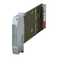
Pos. PS416-INP-400/401 PS416-OUT-400 PS416-OUT-410
햲 Cable exit (bottom standard, top as an option)
햳 Locking mechanism
햴 – Operating mode
selector switch
–
햵 Code switch
햶 Marking strip
햷 – Short-circuit indication for central
disconnection module (ZAA)
햸 – Reset button
햹 Connector plug
햺 – Connection terminal for “ZAA”
햻 Plug-in screw terminal
 Loading...