2-5
01/00 AWB27-1239-GB
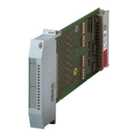
PS416-INP-400/-401
2 Hardware Configuration
Setting addresses In order for the digital input cards to be addressed,
each card must be assigned a separate address.
The addresses are assigned with the coding switch
on each card (see table 2-1 on page 2-6). This
address assigns to each card a special range in the
central unit. The status of the inputs are recorded
there and can be scanned via software. The chapter
“Operation” page 2-13 fully explains the syntax of
addressing the cards.
Two bytes are reserved in the central unit for the 16
inputs of each digital input card. The cards are there-
fore addressed in two steps; only even-numbered
addresses are allowed. The first digital input card is
given the address 0.
왘 Address the cards one after another, starting with
address 0 for the first card. A maximum of
18 digital input cards can be used in each rack. In
this case, the last card is given the address 34.
Table 2-1 shows how poles 1 to 6 of the coding
switch must be set for each card address. It also
shows the input byte used to address the cards via
the software.
 Loading...