Setting addresses
2-7
01/00 AWB27-1239-GB
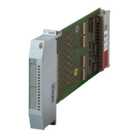
PS416-INP-400/-401
The positions of switches 7 and 8 do not matter.
Figure 2-2: Coding switch set for Address 4
Example
The following figure illustrates a sample assignment
of a rack with input and output cards. It shows how
the marked input cards are addressed.
Figure 2-3: Adressing of digital input cards using an
example configuration
ON
2
34
5
6
7
8
1
POW
NET 400
02 46 81012
INP 400
INP 400
AIN 400
AIN 400
OUT 410
OUT 400
OUT 400
OUT 400
INP 401
INP 401
OUT 400
OUT 400
OUT 400
OUT 410
OUT 410
INP 400
INP 400
INP 400
Slot
34 202
Adr.
 Loading...