Application
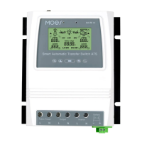
Product introduction
Installation
Auto-Select Voltage Range
The ATS power transfer controller provides reliable operation of an inverter and AC
utility power in one compact device. The ATS switches automatically between the AC
utility power and the inverter, while protecting the inverter against external voltages.
The Dual Power Transfer Controller is used between an Off-Grid Power System and
the Public Utilty Power Supply. The ATS Controller connects separately to 1) Utility
Power 2) Inverter 3) Battery 4) Load. The User Interface allows for both Monitoring of
the ATS Operating State and Adjusting Voltage Setpoints. The Master ON/OFF Switch
is located at the top of the controller for easy access.
The design of your off-grid system and installation of this transfer switch should
only be performed by qualified end users, electricians or technicians authorized and
licensed where required by local codes.
Before installation of this device, please review this manual in its entirety before
beginning.
Install / mount the ATS controller to a clean, and dry surface, and in a suitable
location that will allow free air circulation around the ATS at all times. Insure all
cables are of adequate length to allow for proper strain relief at the ATS connec-
tion block.
Insure all safety protocols are followed. Check all ac power supplies are off and
secured with a safety lock-out tag system to prevent inadvertent power actuation.
All power connection cables must meet minimum wire gauge recommendations set
by standard electrical requirements and your local codes.
Verify all connections are connected and tightened properly! Loose electrical con-
nections will overheat and can damage the ATS and can cause fires.
Do not connect the neutral connector on the user side to ground connection or to a
protective ground connector, as the user outlets have no protective multiple
grounding.
Note! Do not connect the “pe” grounding wire (protective earth) to the neutral
connector.
After insuring the above steps are complied with and you have verified all the con-
nections are properly terminated, proceed with the final connections to the utility
power, inverter, battery, and load (s).
Turn on the master switch located at the top of the ATS.
Perform voltage & ammeter checks on your newly installed system to verify your
ATS is operating within the specified operating parameters.
1.
2.
3.
4.
5.
6.
7.
8.
9.
10.
04
12V system detection voltage range 9V-17V
24V system detection voltage range 18V-30V
48V system detection voltage range 30V-60V
English version