14 Chapter 2. Connections and controls
STATUS Multi-colour indicator displaying status of the lock.
Green Power on, lock disabled.
Orange Lock engaged but error signal goes out of range, indicating the
lock has failed.
Blue Lock engaged and error signal is within limits.
2.1.5 Signal monitoring
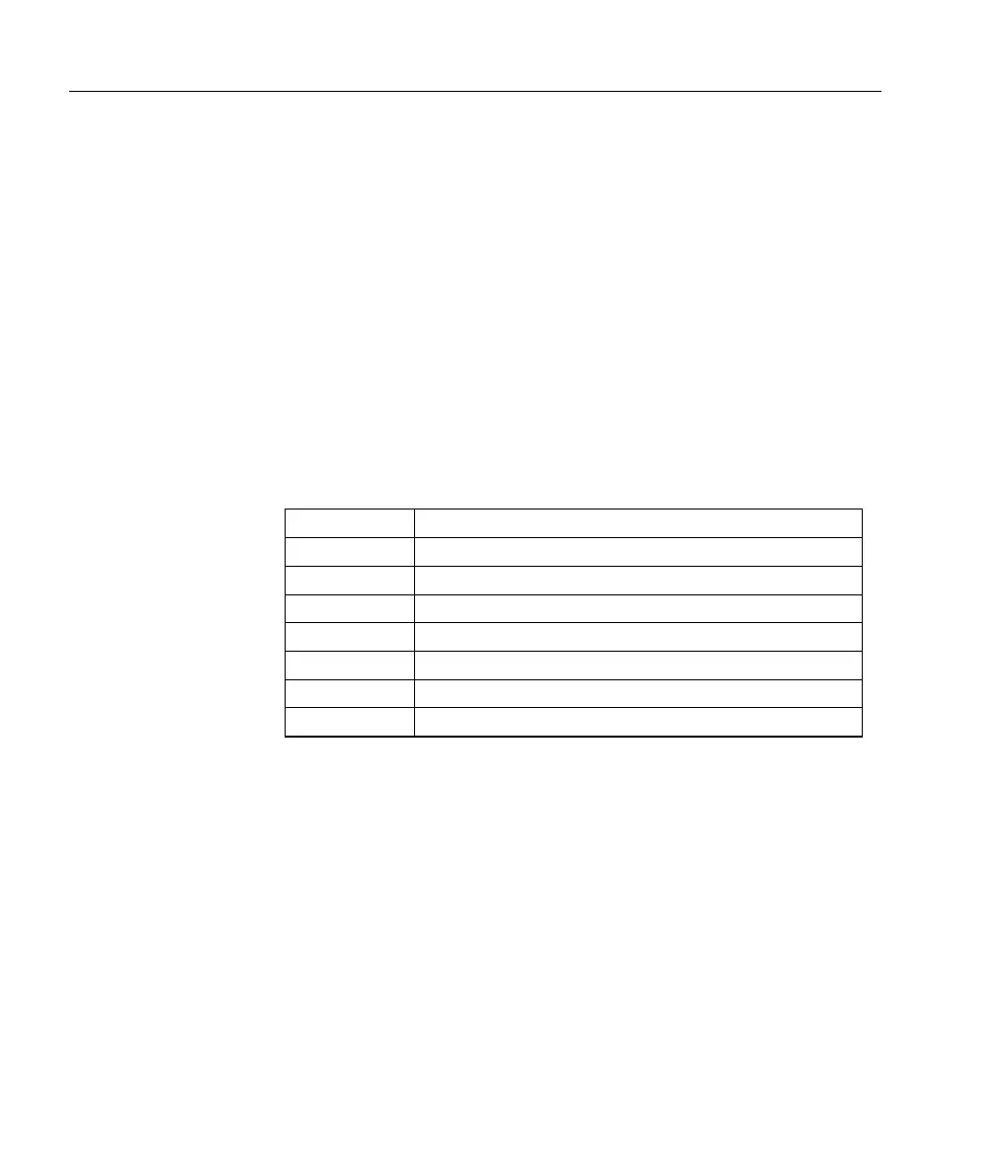
Two rotary encoders select which of the specified signals is routed
through to the rear-panel MONITOR 1 and MONITOR 2 outputs. The
TRIG output is a TTL compatible output that switches from low to high
at the centre of the sweep. The table below defines the signals.
CHA Channel A input
CHB Channel B input
FAST ERR Error signal used by the fast servo
SLOW ERR Error signal used by the slow servo
RAMP Ramp as applied to SLOW OUT
BIAS Ramp as applied to FAST OUT when DIP3 enabled
FAST FAST OUT control signal
SLOW SLOW OUT control signal
 Loading...