2.2 Rear panel controls and connections 15
2.2 Rear panel controls and connections
Serial:
TRIG FAST OUT SLOW OUT MOD IN POWER B POWER A
MONITOR 1MONITOR 2 SWEEP IN GAIN IN B IN A IN
LOCK IN
All connectors are SMA, except as noted. All inputs are over-voltage
protected to ±15 V.
IEC power in The unit should be preset to the appropriate voltage for your country.
Please see appendix B for instructions on changing the power supply
voltage if needed.
A IN, B IN Error signal inputs for channels A and B, typically photodetectors.
High impedance, nominal range ±2.5 V. Channel B is unused unless
the CHB switch on the front-panel is set to PD.
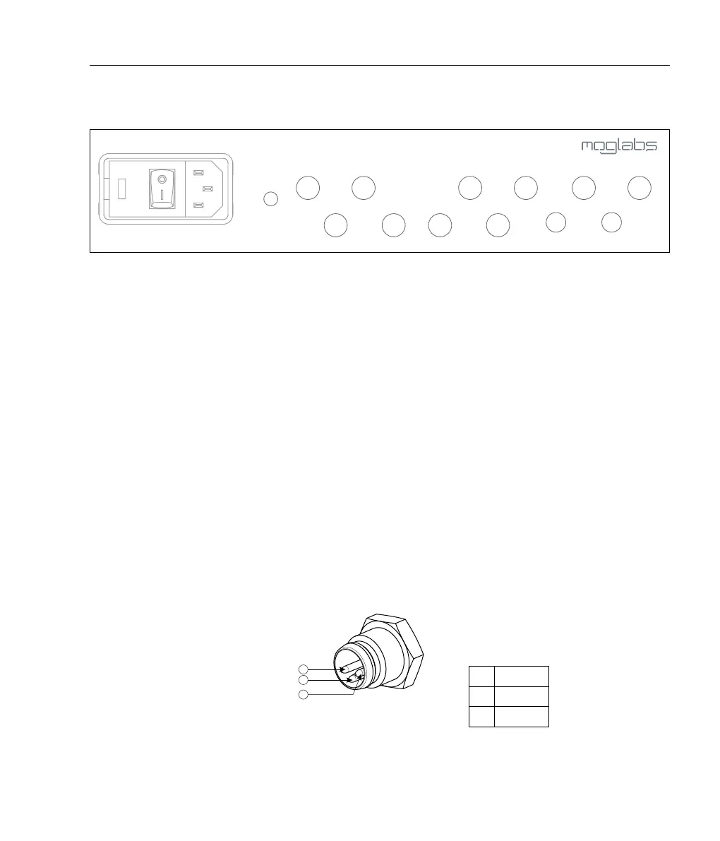
POWER A, B Low-noise DC power for photodetectors; ±12 V, 125 mA, supplied
through an M8 connector (TE Connectivity part number 2-2172067-
2, Digikey A121939-ND, 3-way male). To be used with standard M8
cables, for example Digikey 277-4264-ND. Ensure that photodetectors
are switched off when being connected to the power supplies to
prevent their outputs railing.
1 +12 V
3 −12 V
4 0 V
Figure 2.1: M8 connector pinout for POWER A, B.
 Loading...