16 Chapter 2. Connections and controls
GAIN IN Voltage-controlled proportional gain of fast servo, ±1 V , correspon-
ding to the full-range of the front-panel knob. Replaces front-panel
FAST GAIN control when DIP1 is enabled.
SWEEP IN External ramp input allows for arbitrary frequency scanning, 0 to
2.5 V. Signal must cross 1.25 V, which defines the centre of the sweep
and the approximate lock point.
MOD IN High-bandwidth modulation input, added directly to fast output,
±1 V . Requires
DIP4 to be enabled
1
.
SLOW OUT Slow control signal output, 0 V to 2.5 V. Normally connected to a
piezo driver or other slow actuator.
FAST OUT Fast control signal output, ±2.5 V. Normally connected to diode in-
jection current, acousto- or electro-optic modulator, or other fast
actuator.
MONITOR 1, 2 Selected signal output for monitoring.
TRIG Low to high TTL output at sweep centre.
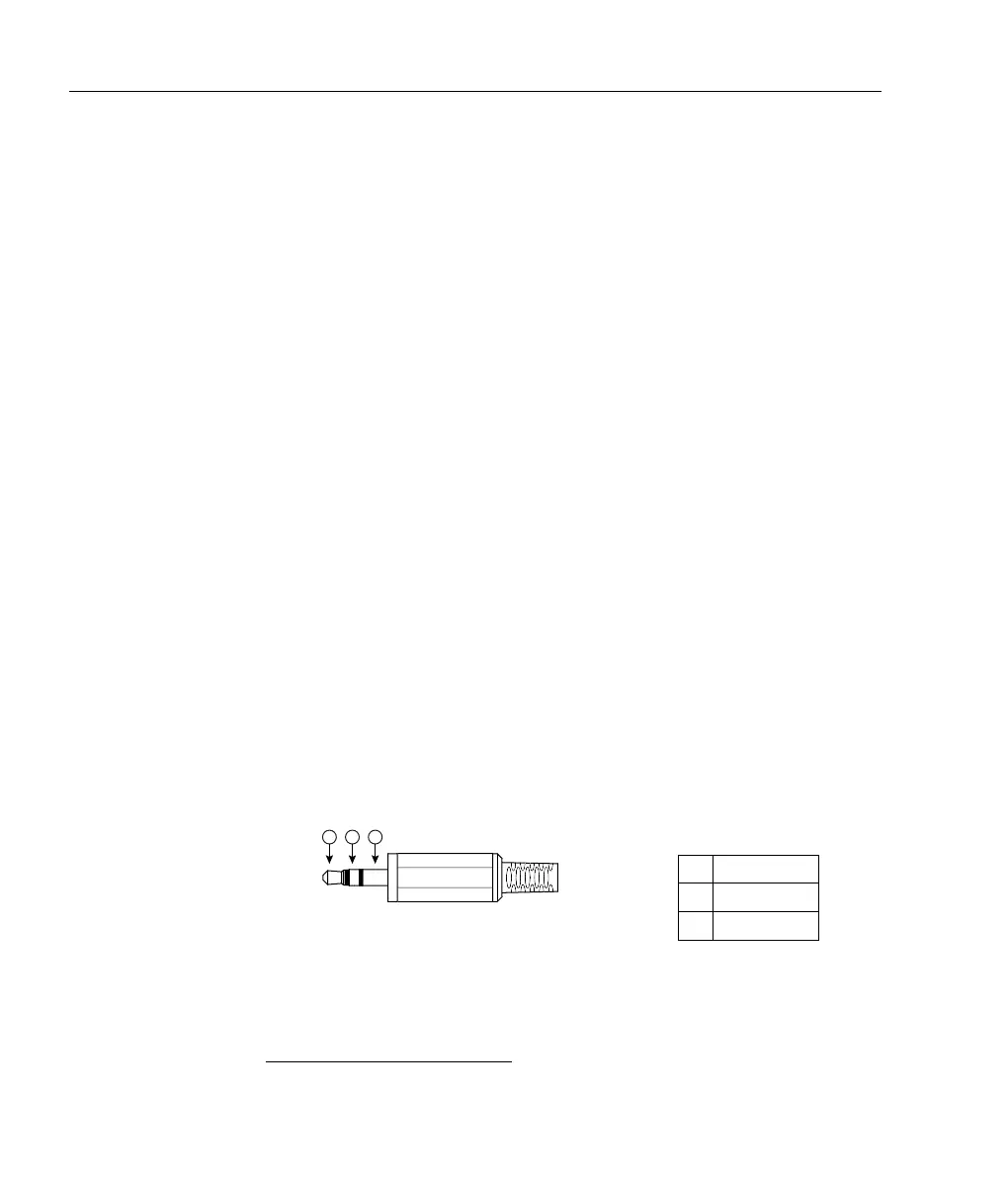
LOCK IN TTL scan/lock control; 3.5 mm stereo connector, left/right (pins 2, 3)
for slow/fast lock; low (ground) is active (enable lock). Front-panel
scan/lock switch must be on
SCAN for LOCK IN to have effect. Digikey
cable
CP-2207-ND provides a 3.5 mm plug with wire ends; red for slow
lock, thin black for fast lock, and thick black for ground.
1 Ground
2 Fast lock
3 Slow lock
Figure 2.2: 3.5 mm stereo connector pinout for TTL scan/lock control.
1
When DIP4 is enabled, MOD IN must be terminated when not in use.
 Loading...