3.3 Optimisation 23
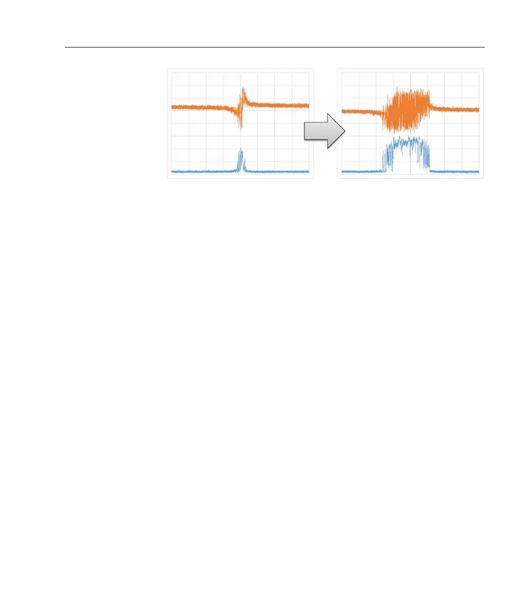
Figure 3.2: Scanning the laser with P-only feedback on the fast output
while scanning the slow output causes the error signal (orange) to become
extended when the sign and gain are correct (right). In a PDH application,
the cavity transmission (blue) will also become extended.
• Set SLOW GAIN to mid-range and SLOW INT to ∼ 100 Hz.
• Set
SLOW mode to “LOCK”. If the servo unlocks immediately,
try inverting the
SLOW SIGN. It may also be necessary to make
small adjustments to the
ERR OFFSET and associated trimpot.
• Adjust
SLOW GAIN and SLOW INT for improved lock stability.
• Some applications may benefit by increasing
FAST DIFF to im-
prove loop response.
3.3 Optimisation
The purpose of the servo is to lock the laser to the zero-crossing of
the error signal, which ideally would be identically zero when loc-
ked. Noise in the error signal is therefore a measure of lock quality.
Spectrum analysis of the error signal is a powerful tool for under-
standing and optimising the feedback. RF spectrum analysers can
be used but are comparatively expensive and have limited dynamic
range. A good sound card (24-bit 192 kHz, e.g. Lynx L22) provi-
des noise analysis up to a Fourier frequency of 96 kHz with 140 dB
dynamic range.
 Loading...