2 Chapter 1. Introduction
Error Error
Frequency f Frequency f
f
0
ERROR OFFSET
∆f
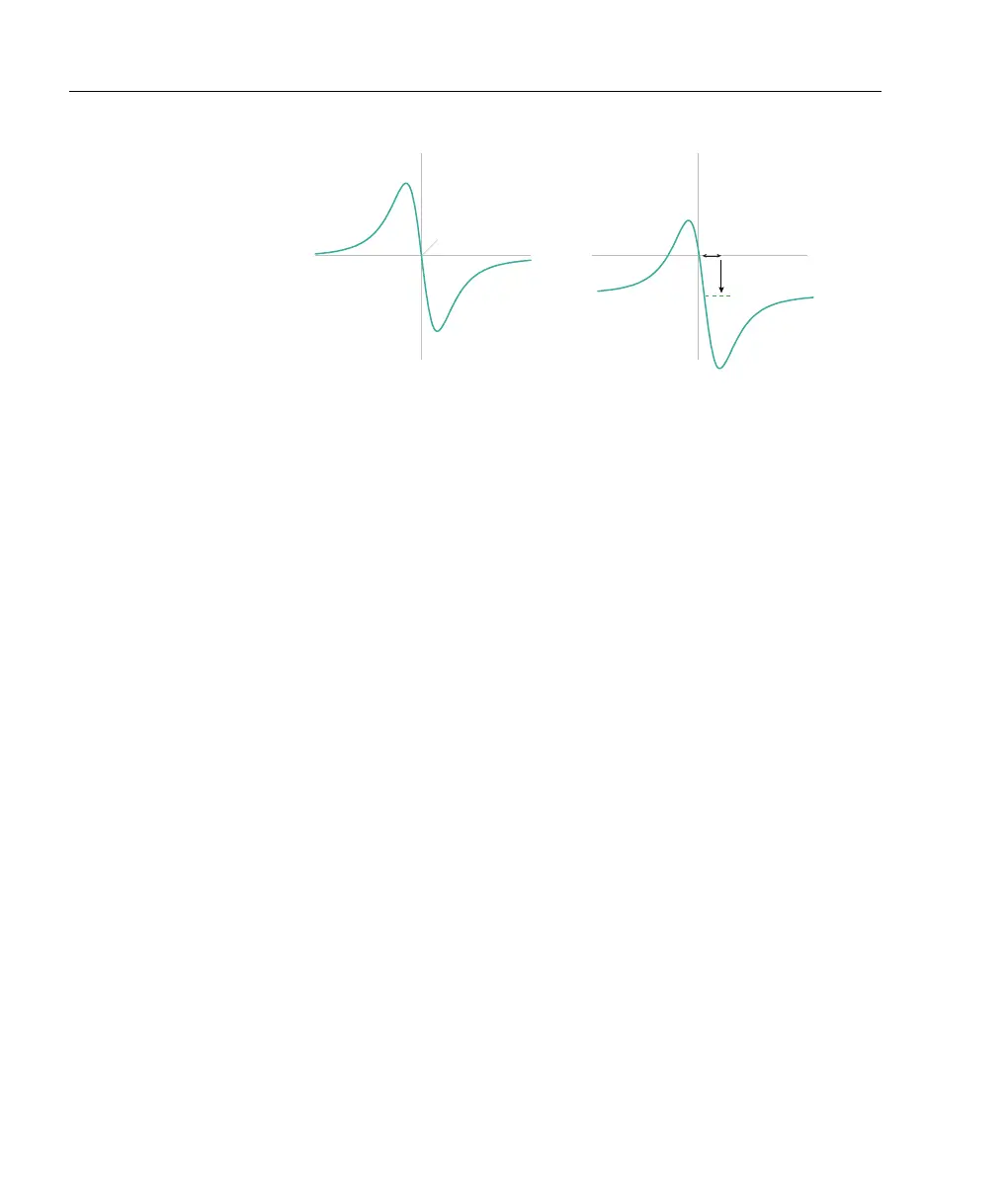
Figure 1.2: A theoretical dispersive error signal, proportional to the dif-
ference between a laser frequency and a setpoint frequency. An offset on
the error signal shifts the lock point (right).
Note the distinction between an error signal and a control signal.
An error signal is a measure of the difference between the actual
and desired laser frequency, which in principle is instantaneous and
noise-free. A control signal is generated from the error signal by a
feedback servo or compensator. The control signal drives an actuator
such as a piezo-electric transducer, the injection current of a laser
diode, or an acousto-optic or electro-optic modulator, such that the
laser frequency returns to the setpoint. Actuators have complica-
ted response functions, with finite phase lags, frequency-dependent
gain, and resonances. A compensator should optimise the control
response to reduce the error to the minimum possible.
The operation of feedback servos is usually described in terms of
the Fourier frequency response; that is, the gain of the feedback
as a function of the frequency of a disturbance. For example, a
common disturbance f
m
is mains frequency, f
m
= 50 Hz or 60 Hz.
That disturbance will alter the laser frequency f by some amount,
at a rate of 50 or 60 Hz. The effect of the disturbance on the laser
might be small (e.g. f = f
0
± 1 kHz where f
0
is the undisturbed
laser frequency) or large (f = f
0
± 1 MHz). Regardless, the Fourier
frequency of the disturbance is either 50 or 60 Hz.