The alarmed device must now he either reset to the Normal condition or
removed from the detection loop.
The Control Panel is now reset to the Normal. condition with the following
!
switches located on the
PCB.
o Momentarily place the Reset switch
(S2)
in
the "reset"
(down) position.
o Place Trouble Silence switch
(Sl)
in the "normal"
(up) position.
o Place Alarm Silence switch
(52)
in the "normal"
(up) position.
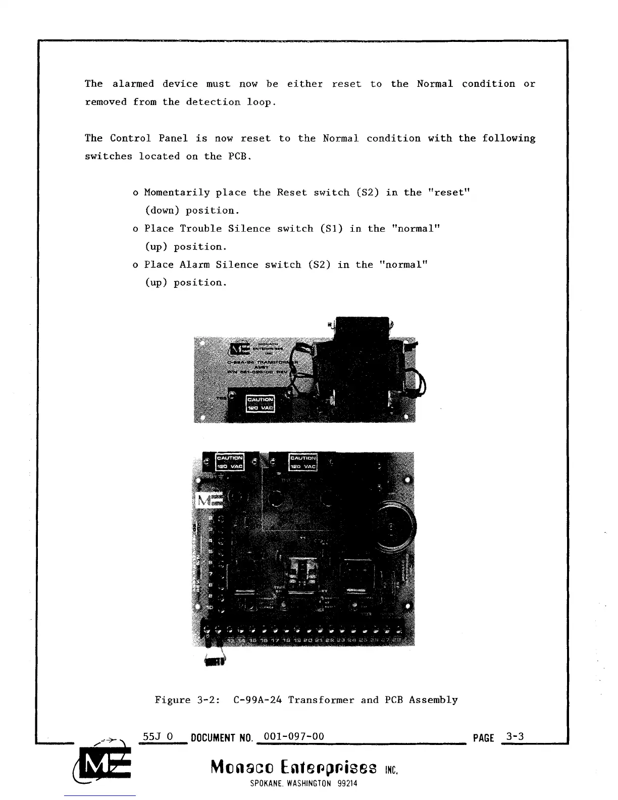
Figure
3-2:
C-99A-24 Transformer and
PCB
Assembly
555
0
DOCUMENT NO.
001-097-00
PAGE
3'3
Monaco
Ente~p~ises
IMC.
SPOKANE. WASHINGTON
99214