4.3 TROUBLESHOOTING
Troubleshooting is presented in Tables 4-1 through 4-3. Each Table
contains one symptom with the Probable Causes and the Corrective Actions.
Determine which symptom applies to the Control Panel. Proceed to the
Appropriate Table and perform the Probable Cause and Correction Steps in
the order given.
Replace all defective parts.
Monaco provides a complete repair service program. Contact Field Service
for additional information.
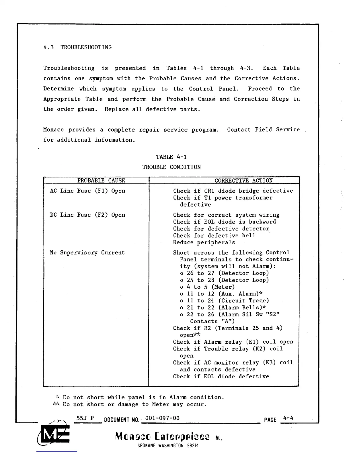
TABLE 4-1
TROUBLE CONDITION
PROBABLE CAUSE
AC
Line Fuse (Fl) Open
DC
Line Fuse (F2) Open
No Supervisory Current
CORRECTIVE ACTION
Check if
CR1
diode bridge defective
Check if T1 power transformer
defective
Check for correct system wiring
Check if EOL diode is backward
Check for defective detector
Check for defective bell
Reduce peripherals
Short across the following Control
Panel terminals to check continu-
ity (system
will
not Alarm):
o 26 to 27 (Detector Loop)
o 25 to 28 (Detector Loop)
o
4
to
5
(Meter)
o
11
to 12 (Aux. A1arm)ik
o
11
to 21 (Circuit Trace)
o 21 to 22 (Alarm Bells)*
o 22 to 26 (Alarm Sil Sw "S2"
Contacts "A")
Check if R2 (Terminals 25 and 4)
ope
nihk
Check if Alarm relay (Kl) coil open
Check if Trouble relay (K2) coil
open
Check if
AC
monitor relay (K3) coil
and contacts defective
Check if EOL diode defective
*
Do not short while panel is in Alarm condition.
J^t.
n4b
DO
not short or damage to Meter may occur.
555
P
DOCUMENT
NO.
001-097-00
PAGE
4'4
Monaco Ente~p~ises
rc.
SPOKANE WASHINGTON
99214