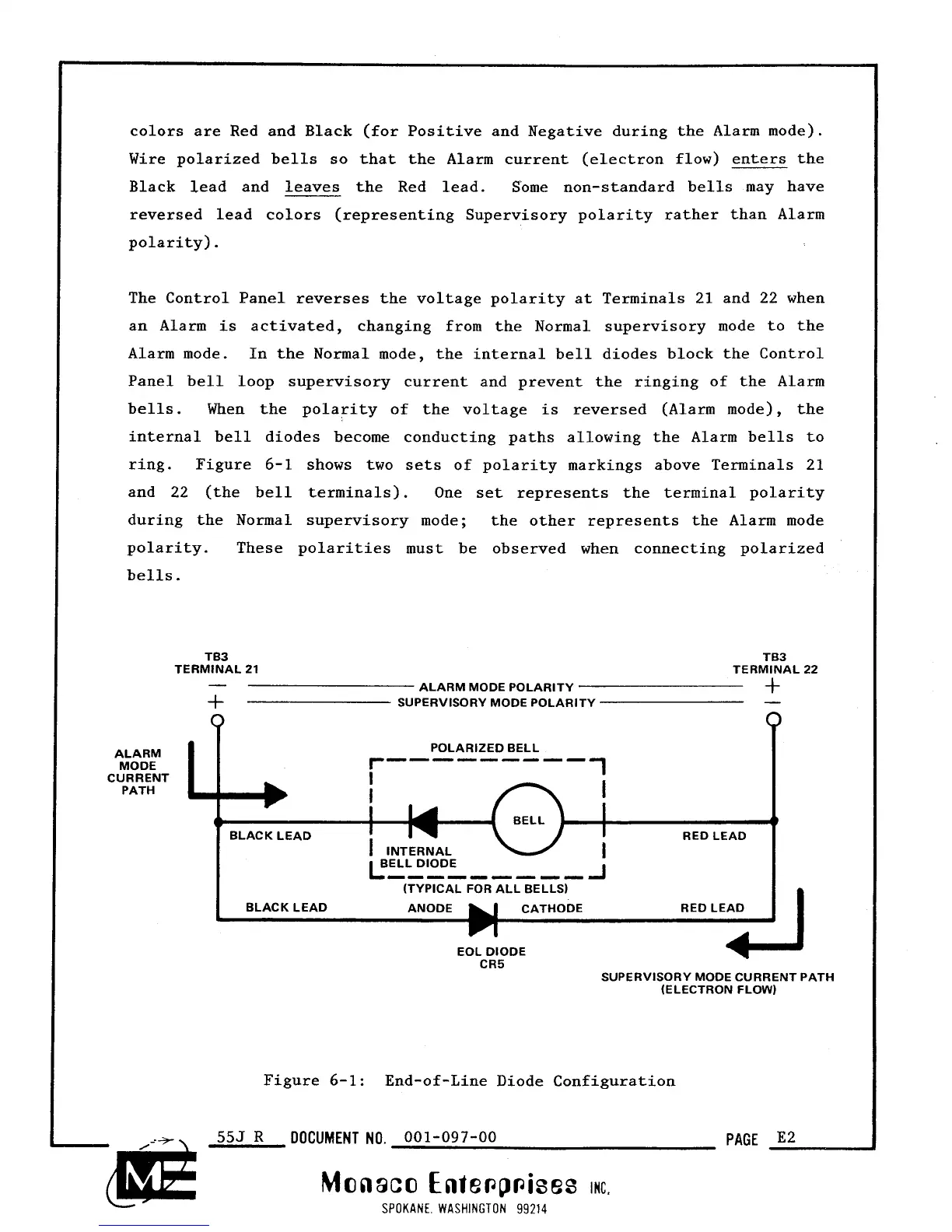
colors are Red and Black (for Positive and Negative during the Alarm mode).
Wire polarized bells so that the Alarm current (electron flow) enters the
Black lead and leaves the Red lead. Some non-standard bells may have
reversed lead colors (representing Supervisory polarity rather than Alarm
polarity).
The Control Panel reverses the voltage polarity at Terminals
21
and
22
when
an Alarm is activated, changing from the Normal supervisory mode to the
Alarm mode. In the Normal mode, the internal bell diodes block the Control
Panel bell loop supervisory current and prevent the ringing of the Alarm
bells. When the polarity of the voltage is reversed (Alarm mode), the
internal bell diodes become conducting paths allowing the Alarm bells to
ring. Figure
6-1
shows two sets of polarity markings above Terminals
21
and
22
(the bell terminals). One set represents the terminal polarity
during the Normal supervisory mode; the other represents the Alarm mode
polarity. These polarities must be observed when connecting polarized
bells.
TB3 TB3
TERMINAL
21
TERMINAL
22
-
ALARM MODE POLARITY
+
SUPERVISORY MODE POLARITY
+
-
Figure
6-1:
End-of-Line Diode Configuration
0
0
555
R
DOCUMENT
NO.
001-097-00
PAGE
E2
Monaco
Ente~p~ises
INC.
SPOKANE WASHINGTON
99214
ALARM
POLARIZED BELL
MODE
r-------
CURRENT
I
1
PATH
I
I
I
I
I
BLACK LEAD RED LEAD
I
INTERNAL
BELL DIODE
I
L
1
(TYPICAL FOR ALL BELLS)
BLACK LEAD ANODE CATHODE RED LEAD
(1
EOL DIODE
CR5
+J
SUPERVISORY MODE CURRENT PATH
(ELECTRON FLOW)