8
English
Deutsch
Deutsch Seite
Français
Français Page
Italiano
Italiano Pagina
Español
Español Página
Nederlands
Nederlands Pagina
Polski
Polski Strona
LINE IN LINE OUT
L / LFE
R
AUTO
ON
OFF
POWER
MAXMIN
LEVEL
200 Hz40 Hz
CUT OFF
-180°0°
PHASE
STANDBY
POWER
HIGH LEVEL INPUT
L
R
USE ONLY WITH A 250V FUSE
8
9
10
ATTENTION! Avant d'ouvrir
l'appareil, retirez la che secteur d'alimentation. Toute
intervention sur le câble secteur et le fusible secteur doit être
eectuée uniquement par du personnel qualié. Protegez
l'appareil de l'humidité et de la chaleur. Plage autorisée de la
température d'utilisation 0
-
40 °C.
À n'utiliser que dans le domaine d'application déterminé.
ATTENZIONE! Staccare la spina di rete prima di aprire
l'apparecchio, e far cambiare il cavo di rete ed il fusibile di rete
solo da persona esperta. Proteggere l'apparecchio dall'umidità e
dal calore. Campo della temperatura d'impiego ammessa 0
-
40 °C.
Usare l'apparecchio solo per lo scopo indicato.
ACHTUNG! Vor Önen des Gerätes Netzstecker ziehen,
Netzleitung und Netzsicherung nur von Fachpersonal wechseln
lassen. Gerät vor Feuchtigkeit und Hitze schützen. Zulässiger
Einsatztemperaturbereich 0
-
40 °C.
Gerät nur für den angegebenen Zweck verwenden.
CAUTION! Remove the mains plug before opening the unit. Leave
replacing of the mains supply cord and mains fuse to qualied
service personnel. Protect the unit against moisture and heat.
Permissible operating temperature range 0
-
40 °C. This product is
not intended
for use other than stated.
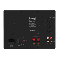
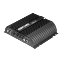
SAM-500D
DIGITAL SU BWOOFER M ODULE
MONACOR INTERNATIONAL • ZUM FALSCH 36 • 28307 BREMEN • GERMANY
230V ~ / 50 Hz / 84 0VA
T4AL
FUSE
230V~/
50Hz
SAM-500D
Amplifier Insertion Module
forSubwoofers
These instructions are intended for non-pro-
fessionals with basic knowledge in DIY speaker
building. Please read the instructions carefully
prior to operation and keep them for later
reference.
1 Status LED
red = standby
green = power amplifier switched on
2 LEVEL control
3
CUT OFF control to set the cut-off frequency
for the subwoofer
4 PHASE control to shift the phase of the out-
put signal compared to the input signal
5
Input LINE IN (RCA jacks) for signals with line
level; when both jacks are connected (e. g.
stereo signal), the signals internally create a
sum signal (mono)
6 Output LINE OUT (RCA jacks) to route the
input signal e. g. to another amplifier
7 Screw terminals HIGH LEVEL INPUT as a sig-
nal input to connect the speaker outputs of
a power amplifier [instead of using the RCA
jacks LINE IN (5)]
8 POWER switch
9
Mains jack for connection to a socket
(230 V/ 50 Hz) via the mains cable provided
10 Support for the mains fuse
Always replace a blown fuse by one of the
same type.
1 Operating Elements
andConnections
English
English Page