Do you have a question about the Monitor 21 and is the answer not in the manual?
Detailed specifications for Monitor 441 and Monitor 422 models.
Describes safe re-lighting, electrical protection, and flue pipe safety.
Responsible for heat production via fuel and air combustion.
Manages fuel flow for efficient combustion.
Supplies power and describes operational phases.
Overview of installation process and information included.
Guidelines for locating the heater and drilling holes for flue pipe.
Specifies electrical requirements and fuel tank guidelines.
Specifies clearances for frontal, overhead, and side installations.
Pictorial views and checklist for fuel storage facilities.
Overview of operation features and performance specs.
Explains controls and indicators for operating the heater.
Covers Manual, Automatic, Economy Plus, and Shutdown.
Covers Out of Fuel, Power Failure, Overheat, and Blown Fuse recovery.
Differentiates periodic and corrective maintenance.
Schedule of tasks for maintaining good operating condition.
Procedure for cleaning the filter and inspecting components.
Covers causes and procedures for efficiency losses.
Method for cleaning heavy soot build-up in the unit.
Covers resistance values, voltage readings, and test points for troubleshooting.
Guides for general checks and specific symptom resolution.
Detailed schematic diagram of the Monitor heater's electrical system.
Shows wiring connections for panel and main printed wiring boards.
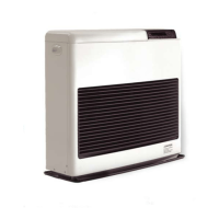
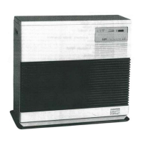
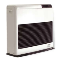
Visual representations of heater components for identification.
Lists of all available service parts with item numbers.
| Brand | Monitor |
|---|---|
| Model | 21 |
| Category | Heating System |
| Language | English |