Do you have a question about the Monitor 441 and is the answer not in the manual?
Details model specifications, fuel type, efficiency, heat rating, output, fuel tank, and consumption.
Lists automatic ignition, dual blowers, thermostat control, built-in timer, and indicator lights.
Highlights safe re-lighting, electrical protection, and flue pipe safety.
Provides an overview of the heater's main components and systems.
Describes the spill tray's function for floor protection and heater stability.
Describes the steel cabinet that houses all internal components.
Explains the system responsible for heat production via fuel and air combustion.
Details the combustion chamber, its connections, and associated parts.
Describes the burner pot's design for supporting efficient combustion.
Explains the assembly designed to promote efficient combustion.
Describes the burner cap's function in shaping the flame.
Explains the flame sensor's role in supervising the flame.
Details the igniter's function in pre-heating and igniting the fuel mixture.
Explains how air is channeled for combustion and heating.
Details the system for maintaining fuel flow for efficient combustion.
Describes options for external fuel storage for the Monitor 422.
Explains the safety mechanism that cuts off fuel during overheating.
Details the valve with auto shut-off and fuel set lever.
Describes the solenoid pump's role in metering fuel flow.
Overview of power supply and operational phases.
Details the microprocessor's functions for safety, control, and timing.
Explains the sensor for gauging room temperature.
Covers devices protecting users and the heater.
Describes insulating covers for hot exhaust lines.
Explains the guard protecting against fan blade contact.
Details the fuses protecting the heater from overloads.
Explains the switches that shut down the heater due to overheating.
Describes the selector for setting reset temperature after power interruption.
Overview of the quick and economical installation process.
Guidelines for heater location and clearances.
Details the hole size and pitch for flue pipe installation.
Lists essential tools for installation and service.
Specifies voltage, frequency, and electrical connection requirements.
Outlines requirements for remotely located fuel tanks.
Explains how to wire the wall-mounted temperature sensor.
Emphasizes compliance with local codes for installation.
Provides steps for safely unpacking the heater.
Guidelines for choosing a heater location.
Details required clearances for frontal, overhead, and side installations.
Instructions for preventing flue pipe freezing in cold climates.
Steps for installing a window kit for venting.
Detailed steps for installing the window kit frame and adapter.
Instructions for installing the special window lock.
Guidance on constructing air and exhaust lines for extension kits.
Illustrates maximum lengths and bends for extension kits.
Illustrates typical installations for kerosene lifter pumps.
Explains using the elbow adapter kit for conversion and venting.
Provides pictorial views of storage facilities and delivery systems.
Illustrates different types of fuel storage like gravity fed tanks.
Discusses safe physical placement of heaters on combustible flooring.
Shows typical fuel line connections for Monitor 441 and 422.
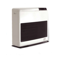
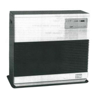
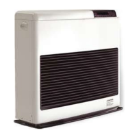
Overview of the easy-to-operate vented kerosene heater.
Lists specifications for Monitor 441 and 422, including efficiency and power.
Lists Monitor 422 performance specs at various heat output settings.
Explains controls and indicators for operating and monitoring the heater.
Details the function of various controls and indicator lights.
Checklist for ensuring operational readiness before startup.
Overview of manual and automatic operation control.
Step-by-step guide for operating the heater manually.
Details on engaging and the benefits of Economy Plus mode.
Steps for programming and operating the heater automatically.
Instructions for setting the current time on the clock.
Steps to program the first automatic time and temperature setting.
Instructions for programming additional time/temperature settings.
How to enable automatic operation mode.
Final step to turn the heater on for automatic operation.
Guide for reprogramming current time and automatic settings.
Information on heat sensor location and mounting.
Procedure for shutting down the Monitor heater.
Symptoms and procedures for refueling the heater.
Step-by-step guide for refueling the capsule fuel tank.
Instructions for resuming operation after power interruptions.
Steps to recover from an overheat condition.
Diagnosing causes of overheating, like air circulation issues.
Procedure for removing the louver assembly for cleaning.
Instructions for cleaning the heater's interior components.
Procedure for recovering from a blown fuse.
Details the operation timing chart for the M-441 model.
Details the operation timing chart for the M-422 model.
Differentiates between periodic and corrective maintenance.
Schedule for tasks to maintain heater efficiency.
Lists suggested maintenance tasks and remarks.
Procedure for inspecting and testing exhaust/air piping for leaks.
Steps to visually inspect the igniter's operation.
Procedure for cleaning the filter in the constant level valve.
Steps to clean the intake fitting on the fusible link valve.
Introduces general remedies for operating difficulties.
Procedure for replacing fuses due to short circuits or malfunctions.
Steps to diagnose and address fuel contamination issues.
Covers causes and procedures for efficiency losses.
States that fuel flow rates are preset and should not be readjusted.
Procedure to remove water deposits and contaminants from the fuel system.
Instructions for cleaning the burn chamber and burner pot.
Procedure for cleaning the fuel inlet nozzle.
Table showing resistance values for various components.
Table showing resistance values for Monitor 22 and 41 components.
Table detailing component voltage readings for AC and DC.
Table detailing component voltage readings for Monitor 22 and 41.
Table showing test point voltages during different operational stages.
Table showing test point voltages for Monitor 22/41.
Lists digital display codes, reasons for indication, and trouble points.
Flowchart for general checks and troubleshooting steps.
Flowchart for diagnosing improper burn mode operation.
Flowchart for diagnosing flame failure and related circuits.
Flowchart for diagnosing no ignition or combustion blower problems.
Flowchart for diagnosing pump and other component failures.
Flowchart for diagnosing fuel feed issues.
Flowchart for diagnosing smoke production and combustion noise.
Flowchart for diagnosing overheat thermostat activation.
Flowchart for diagnosing PCB and fuel contamination issues.
Electrical schematic diagram for Monitor 441.
Diagram showing lead wire connections for Monitor 441.
Diagram showing lead wire connections for Monitor 422.
Details manometer readings for fan speed damper adjustments.
Diagram indicating low and high pressure sides for readings.
Lists service parts for the Monitor 441 with item numbers and descriptions.
Lists service parts for the Monitor 422 with item numbers and descriptions.
Lists service parts for the Monitor 41 with item numbers and descriptions.
Lists service parts for the Monitor 22 with item numbers and descriptions.
| Brand | Monitor |
|---|---|
| Model | 441 |
| Category | Heating System |
| Language | English |