Do you have a question about the Monitor 22 and is the answer not in the manual?
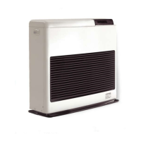
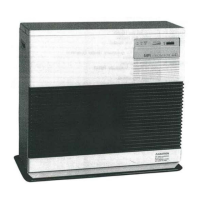
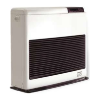
Details on heater specifications, special features, safety features, and general description of the Monitor system.
Description of key components within the combustion system like the chamber, burner pot, igniter, and air system.
Explanation of the fuel delivery system, tanks, valves, solenoid pump, and the electrical system components.
Overview of safety mechanisms, exhaust pipe insulation, fan guard, fuses, overheat protection, and reset temperature.
Guidance on installation introduction, physical placement, drilling requirements, and power needs.
Details on fuel tank requirements, temperature sensor wiring, building codes, and unpacking instructions.
Instructions for heater installation, flue pipe clearances, and installation of window kits.
Procedures for installing window locks, extension kits, and managing flue pipe clearances.
Information on elbow adapter kit uses, fuel tank installation, and final heater placement considerations.
Overview of Monitor heater operation, introduction, and operating specifications for different models.
Description of operating controls and indicators used to manage the heater's performance.
A checklist for pre-operation inspection and details on basic heater operation procedures.
Instructions for manual heater operation, economy plus mode, and automatic heater operation settings.
Guidance on reprogramming the heater, heat sensor placement, and the shutdown procedure.
Steps for handling out-of-fuel situations and recovery after power failure or overheat conditions.
Procedure for recovery from a blown fuse and operation timing charts for M-441 and M-422.
Overview of maintenance types and schedule for periodic upkeep of the Monitor heater.
Procedure for inspecting exhaust and air piping for leaks, blockages, and damage.
Steps to verify igniter operation and clean the fuel constant level valve filter.
Procedures for fuse replacement, cleaning fusible link valve fittings, and addressing fuel contamination.
Introduction to servicing, signs of improper performance, and fuel flow rate measurement.
Procedure for removing water deposits and contaminants from the fuel constant level valve and lines.
Instructions for cleaning the burn chamber and burner pot, including component removal and reassembly.
Guidance on cleaning the fuel inlet nozzle when servicing the combustion chamber and burner pot.
Provides resistance values for Monitor 422/441 and 22/41 components, and voltage readings.
Details test point voltage readings for various operation modes and stages.
Lists failure indications by digital display and provides general diagnostic checks.
Diagnostic flowcharts to identify and correct specific heater symptoms and malfunctions.
Detailed schematic diagram of the heater's printed circuit board and electrical layout.
Illustrates the connection of lead wires to the main printed wiring board for various models.
| Brand | Monitor |
|---|---|
| Model | 22 |
| Category | Heating System |
| Language | English |