Do you have a question about the Monitor 41 and is the answer not in the manual?
Detailed technical specifications for Monitor heaters, including ratings and output.
Highlights key operational and convenience features of the heaters like automatic ignition and timers.
Outlines built-in safety mechanisms for user and appliance protection.
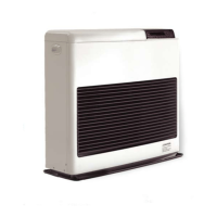
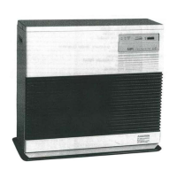
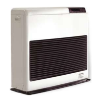
Describes the main parts comprising the Monitor heating system, from spill tray to cabinet.
Details components related to fuel delivery and regulation, including tanks and valves.
Explains electrical systems, microprocessor, sensors, fuses, and safety switches.
Overview of the installation process, tools required, and general considerations.
Covers placement, power, fuel requirements, sensor wiring, codes, and unpacking.
Guidelines for choosing a location and installing the heater unit.
Instructions for flue pipe clearances and window kit installation.
Details on installing extension kits, lifter pumps, and elbow adapter kits.
Guidance on installing fuel tanks, including gravity-fed and pumped systems.
Final steps and considerations for heater placement and connections.
Overview of Monitor heater's ease of use and operating modes.
Performance data and specifications for different models and settings.
Explanation of the heater's controls, buttons, and display indicators.
Step-by-step guide for manual, automatic, and economy modes.
Procedures for handling power failures, overheating, blown fuses, and out-of-fuel.
Timing charts illustrating system operation sequences and states.
Distinguishes between periodic and corrective maintenance for heater upkeep.
Schedule of regular tasks to maintain heater efficiency and performance.
Procedures for specific repairs like fuse replacement and fuel contamination.
Discusses causes and procedures for efficiency losses and performance issues.
Steps for cleaning fuel constant level valve and fuel lines.
Procedures for cleaning the burn chamber, burner pot, and fuel inlet.
Table of resistance values for various heater components.
Table of AC/DC voltage readings for key components during operation.
Voltages to check at specific test points during various operation modes.
Explains digital display codes indicating specific failure modes.
A flowchart for initial troubleshooting steps based on common symptoms.
Detailed diagnostic flowcharts for various operational issues.
Visual representation of electrical connections and printed circuit board layouts.
Diagram showing disassembled parts of the Monitor 441 unit.
List of part numbers and descriptions for the Monitor 441.
Diagram showing disassembled parts of the Monitor 422 unit.
List of part numbers and descriptions for the Monitor 422.
Diagram showing disassembled parts of the Monitor 41 unit.
List of part numbers and descriptions for the Monitor 41.
Diagram showing disassembled parts of the Monitor 22 unit.
List of part numbers and descriptions for the Monitor 22.
| Brand | Monitor |
|---|---|
| Model | 41 |
| Category | Heating System |
| Language | English |