MONITOR
HEATING
SYSTEMS
Section
5:
Servicing
3.
Turn
counter-clockwise to remove combustion
ring.
If
ring does not turn, pull up slightly to
loosen retaining clips.
4.
Use wire brush to clean inside of combustion
chamber.
Vacuum and wipe clean with
a
waste cloth.
5.
If tar is present on
the
bumer bottom, remove
the tar by using
a
flat-bladed screw driver or
wire
brush.then clean the area by using
a
vacuum cleaner etc.
NOTE:
Make sure all air inlet openings are clear.
6.
When cleaning the inside of me bumer pot,
remove
the
igniter and change the burner cloth
by the following procebure.
7.
On the Monitor
422
A.
Apply glue(P/Na&lT) on the burner bottom
as
shown in Figure5-1.
u
Figure
5-1
B.
Put
the burner cloth on the burner bottom,
afterwards press and straighten
out
the
burner cloth so that
it
is glued flat and even
on the burner bottom.
8.
On the Monitor
44l
A.
Apply glue arround
the
burner cloth
as
shown in Figure
5-2.
1
[jy-'m
I
Oue
\
.
b
--___..'
*OePl
'Is-
Ftgure
5-2
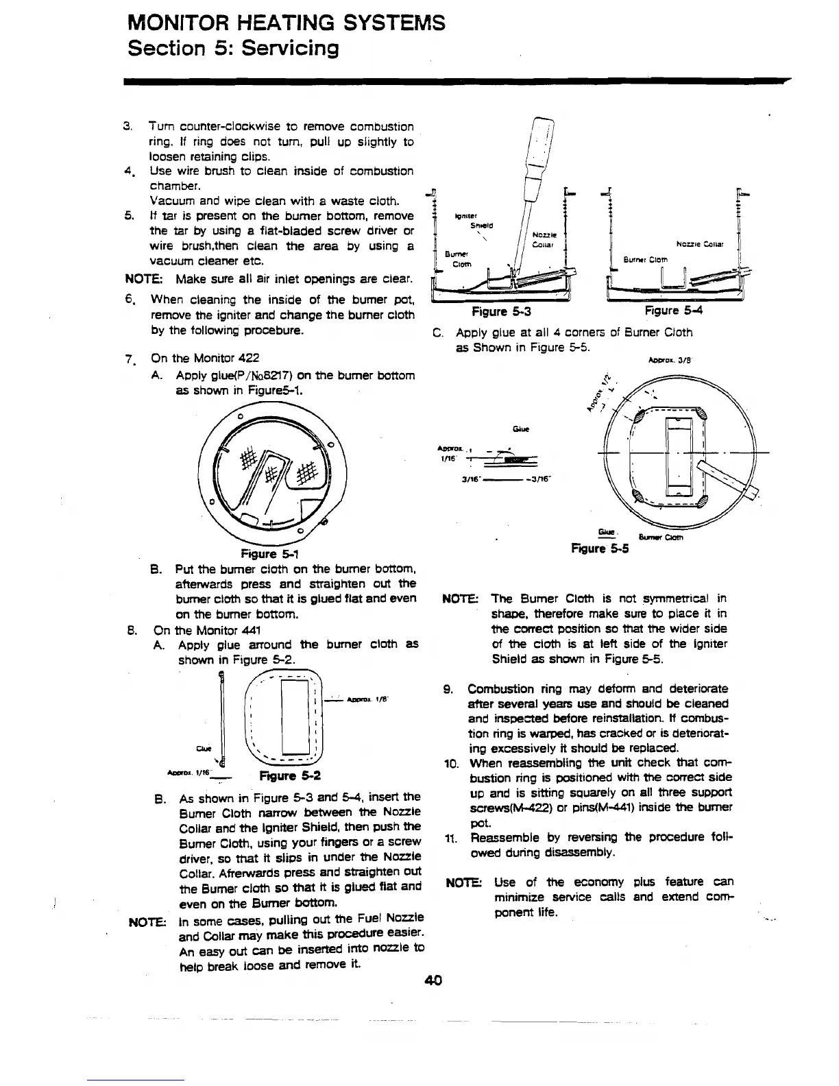
B.
As
shown in Figure
5-3
and
5-4,
insert the
Burner Cloth
narrow
between
the
Nozzle
Collar and the Igniter Shield, then push
the
Bumer Cloth, using your fingers or a screw
driver, so that
it
slips in under the Naule
1
Nozzle Collar
)I
Figure
5-3
Rgure
54
C.
Apply glue at all
4
corners of Burner Cloth
as
Shown in Figure
5-5.
Awroa.
318
NOTE:
The
Burner Cloth is not symmetrical in
shape, therefore make sure to place
it
in
the
correct position so that
the
wider side
of
the
cloth
is
at
lett side of the lgniter
Shield
as
shown in Figure
55.
9.
Combustion ring may deform and deteriorate
after several years
we
and should
be
cleaned
and inspected before reinstallation.
If
combus-
tion ring is
warped,
has cracked or is detenorat-
ing excessively
it
should
be
replaced.
10.
When reassembling
the
unit check that com-
bustion ring is positioned with
the
correct side
up and is sitting squarely on all three support
screws(~22) or pins(Ni-441) inside
the
bumer
Pot.
11. Reassemble by reversing the procedure foll-
owed during disassembly.
Collar.
Afrerwards press and straighten out
the Bumer cloth so that
it
is
glued fiat and
NOTE:
Use of
the
economy
plus
feature can
even on
the
Burner battom.
minimize service calls and extend corn-
NOTE:
in some mes, pulling out the Fuel Nozzle
ponent
life.
and Collar may make
this
procedure easier.
An
easy
out
can
be
inserted into nozzle
to
hetp break loose and remove
it.
40