- 14 -
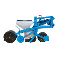
2. Montage du capteur de roue
- Positionner les deux aimants A sur leurs supports B (Fig.1), la face rouge
de l’aimant doit être positionnée face au capteur de roue C, puis fixer les
deux supports sur la roue en les positionnant à 180° l’une de l’autre par
rapport au centre de la roue.
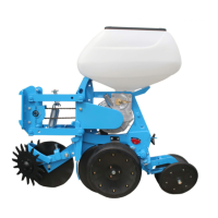
- Le capteur de roue doit être monté sur le bloc roue à l’aide d’une patte de
fixation D (Fig.2) et la distance entre le capteur et les aimants est de 4
mm.
- Il est nécessaire après montage et avant chaque utilisation de vérifier le
bon fonctionnement électrique et mécanique.
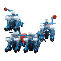
3. Montage des capteurs de fin de course sur élément NG+
- Fixer le capteur E (Fig.3) sur l’élément à l’aide de 2 vis.
- Fixer la vis F grâce aux 2 écrous de façon à ce que le capteur soit actionné
lorsque le semoir est en position basse (position de travail).
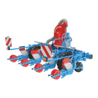
4. Montage des capteurs de fin de course sur élément MS
- Fixer le capteur E (Fig.4) sur son support G à l’aide de 2 vis.
- Fixer le support de façon à ce que le capteur soit actionné lorsque le
semoir est en position basse (position de travail).
2. Mounting the wheel sensor
- Place the two magnets A on their bracket B (Fig 1). The red face of the
magnet shall be located in front of the wheel sensor C. Then secure both
brackets on the wheel placing them 180° the one with the other in relation
with the centre of the wheel.
- The wheel sensor shall be mounted on the wheel unit by means of a
bracket D (Fig.2) and the distance between the sensor and the magnets is
4 mm.
- After assembly, and before each use, it must be checked that the electrical
and mechanical systems are operating correctly.
3. Mounting the travel end sensors on the NG+ elements
- Secure the sensor E (Fig.3) on the element using 2 screws.
- Secure the screw F using the 2 nuts so that the sensor is operated when the
seeder is in the low position (working position).
4. Mounting the travel end sensors on the MS elements
- Secure the sensor E (Fig.4) on its bracket G using 2 screws.
- Secure the bracket so that the sensor is operated when the seeder is in the
low position (working position).
Fig. 2
Fig. 1
Fig. 3
Fig. 4
 Loading...