EasyManua.ls Logo

monster tower MT1 - User Manual

Default Icon
12 pages
Print Icon
To Next Page IconTo Next Page
Loading...
Reference 09Aug2014 V16 Pg 1 of 12 Copyright 2002-2014, Monster Tower, Inc.
Installation Instructions
And Owners Manual
MT1
Monster Tower, Inc.
5714 US Hwy 411 S
Maryville, TN 37801
Phone: 877-77-Tower or 865-934-1290
Fax: 877-232-6538 or 770-234-3833
www.MonsterTower.com
Support@MonsterTower.com
Reference 9August2014V16
It is critical to lightly lubricate bolt threads with included Anti-Seize
before installing Nylock Nuts to prevent the precision stainless steel
hardware from galling and locking, even if you are test-fitting parts together
before installation.
Leave Legs and Top Section protected with bubble wrap sleeves, removing
only the ends as needed, to protect the boat and tower during installation.
THANK YOU FOR YOUR BUSINESS. IF YOU ARE NOT COMPLETELY SATISFIED
IN ANY WAY WITH YOUR NEW MONSTER TOWER, PLEASE CONTACT US
IMMEDIATELY. Our entire purpose as a company is to create great products at
affordable prices that our customers love.
IMPORTANT
Please take a few minutes to read the installation instructions and become
familiar with the Monster Tower parts and installation before beginning to ensure
a high quality, trouble free installation. If you have any questions during your
installation give us a call at 877-77-Tower or e-mail Support@MonsterTower.com
Question and Answer IconNeed help?

Do you have a question about the monster tower MT1 and is the answer not in the manual?

Summary

Monster Tower MT1 Installation and Owners Manual

Important Installation and Usage Notes

Getting to Know Your Monster Tower

Assembly Diagram and Parts List

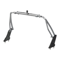
Illustrations of tower components and a detailed list of all parts included in the kit for identification.

Monster Tower Hardware and Tools

Included Hardware List

Comprehensive list of all metric and inch dimension hardware provided with the Monster Tower assembly.

Required and Optional Installation Tools

Essential and supplementary tools needed for a successful installation of the Monster Tower.

Layout and Planning for Installation

Positioning and Folding Strategy

Determining optimal tower placement and ensuring correct folding for storage and boat compatibility.

Pre-assembly of Leg Ends and Base Connections

Steps for assembling leg ends, Heim joints, and base swivel connections prior to mounting.

Rear Base Mounting and Placement

Locating and Marking Rear Base Positions

Guidance on identifying obstructions and marking precise locations for rear base mounting on the boat.

Front Base Placement and Attachment Preparation

Optional Front Leg Assembly and Base Location

Using front legs to check for obstructions and finalize front base mounting points.

Drilling and Rear Base Installation

Hole Preparation and Drilling Techniques

Detailed instructions for drilling clean mounting holes through the boat's hull material.

Mounting Rear Bases and Reinforcements

Procedure for installing rear bases, Monster Paws, and backing plates, including material reinforcement.

Front Base Installation and Tower Assembly

Connecting Rear Legs and Installing Front Bases

Attaching the rear legs to the boat bases and completing the front base installation process.

Final Tower Adjustments and Locking

Centering and Securing the Tower Structure

Ensuring the tower is centered and locked in place by tightening setscrews and anchor bolts.

Drilling and Bolting Mating Swivels

Procedure for drilling and installing anchor bolts through tower swivels for maximum rigidity.

Using and Operating Your Monster Tower

Folding, Storing, and Protecting the Tower

Steps for folding the tower for storage, using protective padding, and general care.

Towing Safety and Noise Troubleshooting

Guidelines for towing with the tower up or down, and addressing any operational noise or looseness.

Appendix and Accessories

Wiring Instructions for Accessories

Guidance on routing wires for lights and speakers through the Monster Tower's structure.

Resources and Additional Tower Components

Information on helpful resources, technical documents, and available accessories for the Monster Tower.

Overview

The Monster Tower is a wakeboard tower designed for boats, featuring an innovative and affordable design that is easy to install. It is engineered to be silent and stiff when correctly installed, preventing rattling or noise.

Function Description:

The primary function of the Monster Tower is to provide an elevated tow point for wakeboarding, enhancing the wakeboarding experience. Its design allows for adjustment to different boat widths and mounting locations, and it can be folded down for storage or trailering. The tower also serves as a platform for mounting various accessories such as wakeboard racks, speakers, light bars, and mirrors, with provisions for internal wiring to keep cables hidden.

Important Technical Specifications:

  • Mounting Dimensions:
    • Rear bases: Positioned to allow the top section to rest on the boat's floor, rear seat, or sun pad when folded.
    • Front bases: 40” to 70” apart from the rear bases, with an optimal range of 48” to 60”.
  • Hardware: Utilizes precision stainless steel hardware.
    • M8 x 60 SHCS / Washer / Nylock (5/16-18 x 2"): For base to boat connection (Qty: 8).
    • M12 x 85 SHCS / Washer / Nylock (1/2-13 x 3-1/2"): For base to base swivel connection (Qty: 4).
    • M12 x 35 SHCS (1/2-13 x 1-3/8"): To attach rod end to base swivel (Qty: 4).
    • M12 Rod End Bearings (Heim Joint) (1/2" Rod End Bearing): For base swivel to rod end support (Qty: 4).
    • M12 Flat Hex Nut (1/2" Hex Jam Nut): Jam nut for rod end (Qty: 4).
    • M12 x 75 SHCS / Washers / Nylock (1/2" x 3"): For front leg swivels to top section (Qty: 2).
    • M12 x 12 Set Screw (preinstalled) (3/8" x 1/2"): To lock rear swivel in collar (Qty: 4).
    • 3" x 2" Metal Backing Plate: For under deck (Qty: 4).
    • Monster Paw Backing Pads (3" x 2"): Pads to boat mounts (Qty: 8).
    • 2-1/2" Teflon Fender Washer: For front legs & top section swivel (Qty: 2).
    • M8 x 55 SHCS / Washers / Nylock (5/16" x 2"): For rear swivel / leg anchors (Qty: 4).
    • M12 Quick Release Knobs (M12 x 35 - Item 3): Supplied hardware (Qty: 2).
    • M10 x 55 SHCS / Washers / Nylock (3/8" x 2"): For rear leg to top section (Qty: 2).
  • Torque Specifications:
    • M12 Nylock Nuts: 65 ft-lbs.
    • M12 x 35 Bolt: 30 ft-lbs.
    • M10 x 40 Nylock Nuts: 50 ft-lbs.
    • Front leg swivels with grease or Teflon washer: 20-30 ft-lbs.
    • Front leg swivels without grease or Teflon washer: 70 ft-lbs.
    • Anchor bolts (Item 15): 30 ft-lbs.
  • Material: Powder coated aluminum (black or white). Fiberglass mounting areas should be at least 3/8" thick; reinforcement with marine-grade plywood or additional fiberglass may be necessary.
  • Wiring: Internal wiring is possible through the rear legs and top section cross member.
    • Rear leg holes: 1" away from weld lines.
    • Top section cross member holes: 3" from weld line to clear rotating collar assembly.
    • Maximum hole size: 1½".

Usage Features:

  • Adjustability: The tower features fixed leg swivels at the top of each leg that mate to swivels on the top section, allowing front or rear legs to move closer or farther apart to adjust to different boat widths. Rear swivels on the top section can rotate in the rear swivel collar, enabling further adjustment for mounting locations.
  • Folding Mechanism: The tower can be folded down flat for storage or trailering by removing Quick Release bolts from the front bases. Heim joints facilitate the pivot towards the back of the boat.
  • Heim Joint Functionality: The Heim joint serves three purposes:
    1. Allows the base to mount on slightly angled boat surfaces.
    2. Enables rear legs to rotate for folding down the tower.
    3. Prevents lateral movement of the tower from stressing the boat.
  • Accessory Integration: Designed to accommodate various Monster Tower accessories like wakeboard racks, speakers, light bars, and mirrors. Internal wiring channels allow for a clean installation of electronic accessories.
  • Durability: Constructed with powder-coated aluminum and stainless steel hardware for marine environments.
  • Quiet Operation: Engineered for silent operation; any rattling or noise indicates an installation issue that needs to be addressed.

Maintenance Features:

  • Anti-Seize Lubricant: Critical for preventing galling and locking of precision stainless steel hardware threads. A thin film must be applied to all bolt threads before installing Nylock Nuts, even during test-fitting.
  • Re-torquing: All hardware, especially M12 Nylock nuts, must be re-torqued after each of the first few uses and then checked regularly to ensure tightness and prevent rattling.
  • Touch-Up Paint: Rustoleum Non-Aerosol Gloss Black/White paint with an Art-kit brush can be used to touch up chips or scratches on the powder-coated tower.
  • Protection During Installation: Bubble wrap sleeves on legs and the top section should be left on as long as possible to protect the boat and tower from scratches during installation. Masking tape can be used on the deck.
  • Drilling Procedures: Specific drilling steps are provided to ensure clean holes through gelcoat and fiberglass, including running the drill in reverse to prevent chipping and chamfering edges.
  • Waterproof Seal: Non-adhesive caulk or sealant can optionally be added between the top of the boat and the Monster Paw to ensure a waterproof seal.
  • Storage Protection: When folding the tower down, use vests, koozies, or other padding to protect the boat and tower where components touch.
  • Warranty: Monster Tower offers a 5-year warranty covering material cracks, fractures, or structural failures due to manufacturing defects. This warranty excludes anodizing, powder-coated surfaces, and hardware corrosion, as well as modifications or improper use.

monster tower MT1 Specifications

General IconGeneral
Brandmonster tower
ModelMT1
CategoryBoating Equipment
LanguageEnglish

Related product manuals