MOONEY INTERNATIONAL CORPORATION
M20V SERVICE AND MAINTENANCE MANUAL
Page
Date
14
MAR 2017
Rev Date
-WARNING-
AVOID MAGNETIC FIELDS IN THE VICINITY OF
THE ELECTRONICS MODULE ASSEMBLY. DE-
PLOYMENT OF THE SYSTEM MAY OCCUR.
-WARNING-
WHEN REMOVING A SEAT FROM THE AIR-
CRAFT, VERIFY THAT THE AAIR RESTRAINT IS
NOT BUCKLED AND DISCONNECT CABLE IN-
TERFACE ASSY FROM THE END- RELEASE
BUCKLE ASSY SAA CONNECTOR BEFORE
REMOVAL OF THE SEAT. AN ELECTRICALLY
CONNECTED AAIR RESTRAINT SYSTEM AND
BUCKLED SEAT BELT MAY RESULT IN DAM-
AGE TO THE EQUIPMENT OR DEPLOYMENT
OF THE SYSTEM.
-WARNING-
THE INFLATOR ASSEMBLY IS A STORED,
GAS/ENERGETIC MATERIAL DEVICE. SEVERE
PERSONAL INJURY OR BODILY HARM MAY
BE CAUSED BY MISUSE AND/OR TAMPERING.
DO NOT TAMPER WITH OR MISHANDLE THE
PRODUCT IN ANY WAY. NEVER ATTEMPT TO
OPEN THE INFLATOR TO SERVICE THE IN-
FLATOR SYSTEM. NEVER APPLY ELECTRICAL
CURRENT TO THE ELECTRONICS CONNEC-
TION.
-CAUTION-
DO NOT DROP THE AAIR EMA. DAMAGE TO
THE ELECTRONICS, BATTERY, OR SENSOR
MAY OCCUR.
-CAUTION-
IF SEATBELT AIRBAG REPLACEMENT IS NOT
IMMEDIATELY POSSIBLE, COVER INFLATOR
NOZZLE TO PROTECT FROM DEBRIS.
Equipment and Materials Required
The following items are required to remove the AAIR
System.
Description
Part Number
Repairman Tool Kit Standard Issue
Safety Glasses Standard Issue
Screwdriver Bit Set, Hex
Drive
Standard Issue
Torque Wrenches, In.
Lb. Type to accommo-
date 5 to 130 In. Lbs of
torque
Standard Issue
Thread Locking Com-
pound, Loctite 242
Loctite Corporation
1- 800- LOCTI TE
(562- 8483)
Removal
-CAUTION-
VERIFY AAIR SYSTEM IS UNBUCKLED BE-
FORE ANY REMOVAL/REPLACEMENT OF
SYSTEM COMPONENTS.
Disconnect the SAA connector(s) (yellow) from the
Cable Interface Assy by sliding the Red Locking Tab
(Figure 25- 4) backwards to the unlocked position, de-
pressing the Yellow Tab, and then pulling apart both
connector halves
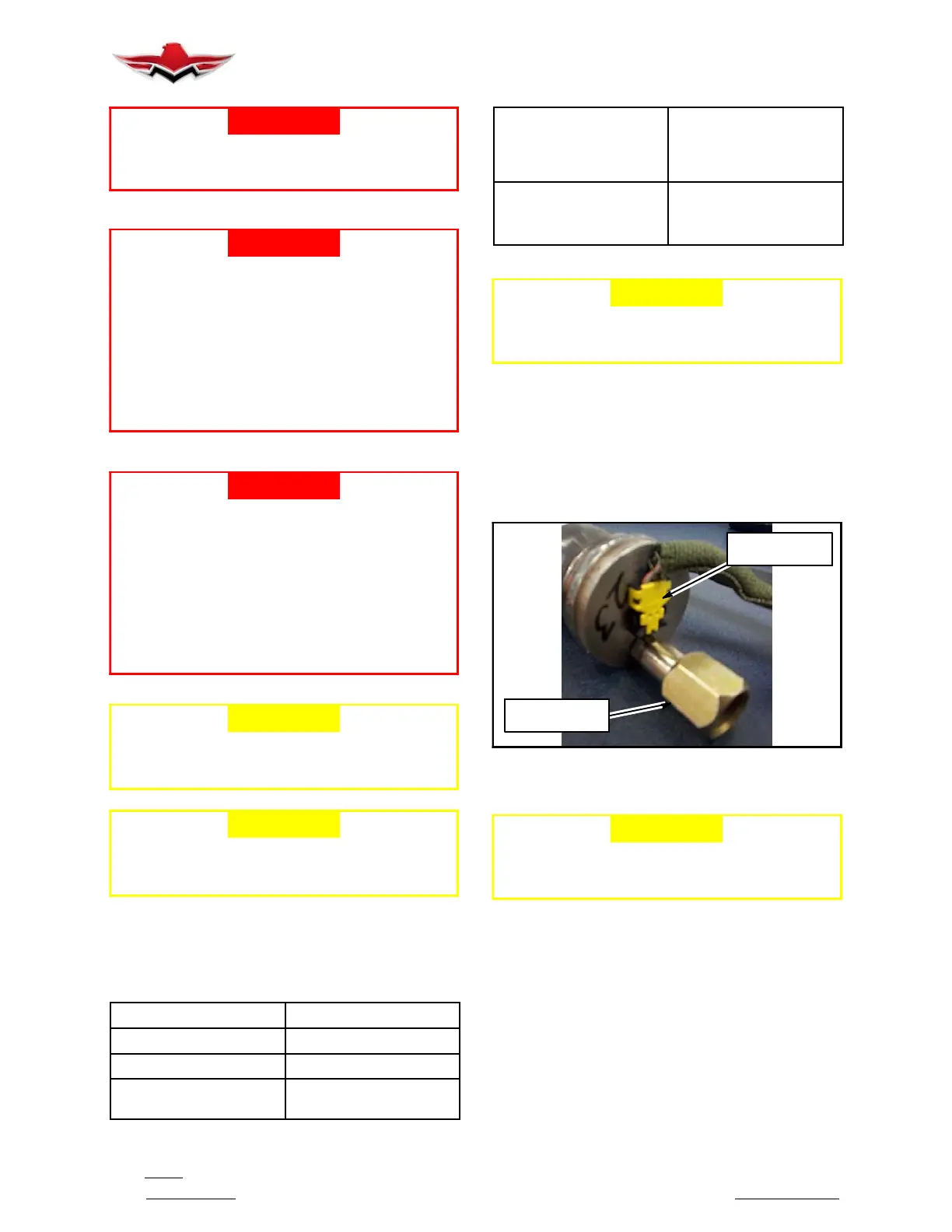
1. Remove squib connector from the Inflator by
squeezing both sides of the connector and gently pull-
ing away from the Inflator (Figure 25- 4).
SQUIB
CONNECTOR
INFLATOR
HOSE FITTING
ELECTRICAL AND HOSE CONNECTOR OF IN-
FLATOR ASSEMBLY
FIGURE 25- 4
-CAUTION-
If replacement of Three- Point Airbag Belt is
not immediately possible, cover Inflator hose
connector to protect from debris.
2. Disconnect the gas hose(s) from the Inflator Assy(s).
The gas hose barb is Loctite coated which makes it a
very secure fit. Use a second back- off wrench for loos-
ening fitting. DO NOT damage crimp end of gas hose if
using vise grips.
3. Loosen the Inflator Assembly from its mounting hard-
ware (refer to Mooney installation instructions/drawing
140345, Restraint Instl - Airbag, or for Aftermarket
installations, AmSafe Installation drawings 509760 -
pilot- co- pilot seats or 509780 - passenger seats for
specifics on attaching hardware for Inflator Assembly).
4. Remove the Inflator Assy(s) from mounting brackets.
25-10-03
 Loading...


