MOONEY INTERNATIONAL CORPORATION
M20V SERVICE AND MAINTENANCE MANUAL
Page
Date
15
MAR 2017
Rev Date
5. After removal of Inflator(s), replace Shipping Cap(s)
in the hose connector fitting. See Table 1 for torque val-
ue.
6. Remove Three- Point Airbag Belt inertia reel(s) or
manual adjustor attachment point from aircraft struc-
ture and seatbelt from mounting point Restraint Instl -
Airbag, or for Aftermarket installations, refer to AmSafe
Installation drawings 509760 - pilot, co - pilot seats or
509780 - passenger seats).
7. Remove End- Release Buckle Assy(s) housing from
seat or aircraft structure mounting point or for Aftermar-
ket installations, refer to AmSafe Installation drawings
509760 - pilot - co- pilot seats or 509780 - passenger
seats).
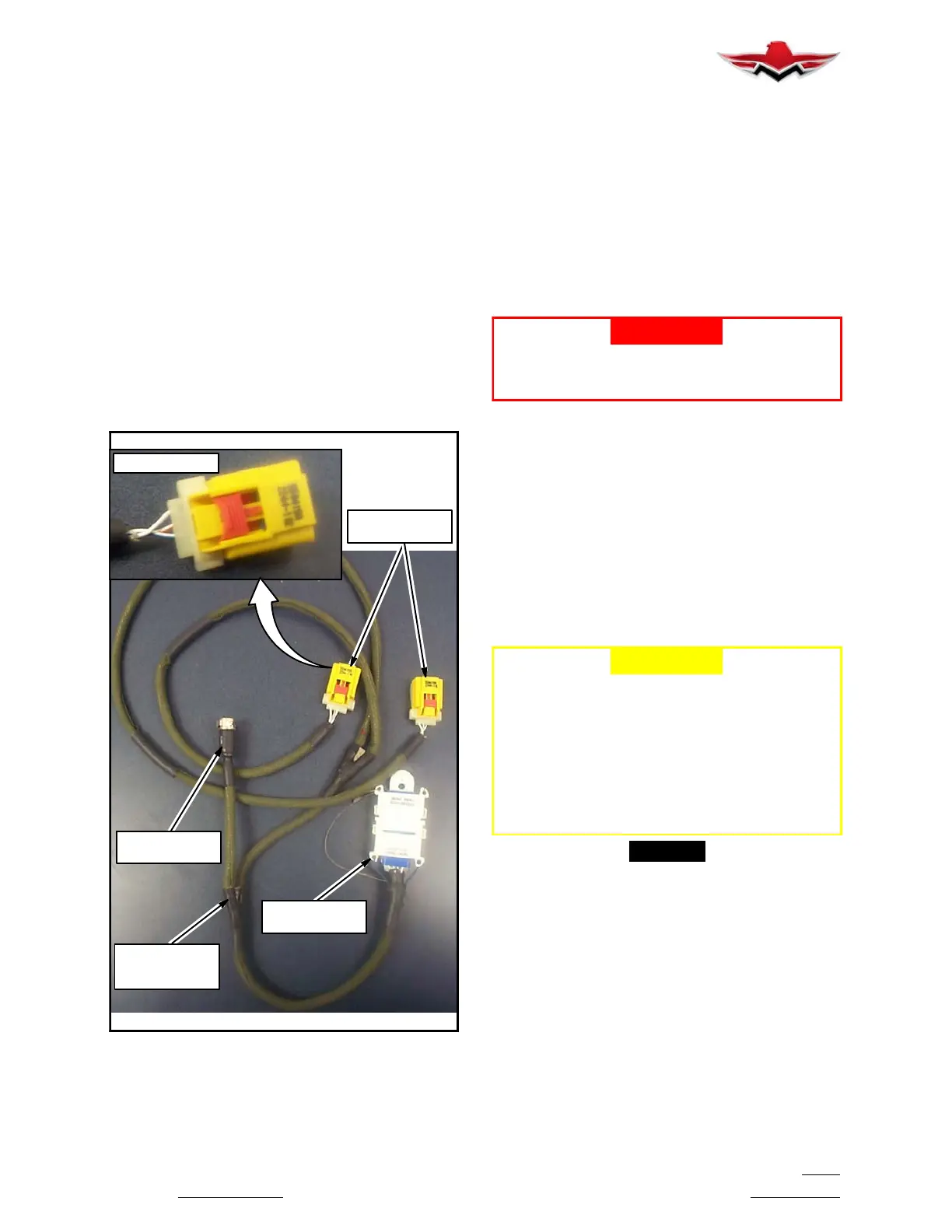
8. Disconnect the Cable Interface Assembly from the
EMA (Figure 25- 5) by depressing locking mechanism,
releasing the connector halves.
SAA
CONNECTORS
EMA
CONNECTOR
DIAGNOSTIC
CONNECTOR
CABLE
INTERFACE
ASSEMBLY
LOCKING TABS
ELECTRICAL AND HOSE CONNECTOR OF IN-
FLATOR ASSEMBLY
FIGURE 25- 5
9. Remove Cable Interface Assembly.
10. Remove EMA from mounting hardware (Aftermar-
ket installations, refer to AmSafe Installation drawings
509760 - pilot, co- pilot seats or 509780 - passenger
seats).
Replacement
Replace all AAIR components with same part number
as that of removed assembly. (for Aftermarket installa-
tions, refer to AmSafe Installation drawings 509760 -
pilot- co- pilot seats or 509780 - passenger seats, or
SICA Parts List to define cable routing.
-WARNING-
AVOID MAGNETIC FI ELDS AT ALL TIMES IN
THE VICINITY OF THE EMA. DEPLOYMENT OF
THE SYSTEM MAY OCCUR.
1. Before replacing new Inflator(s) Assy(s), unscrew
the Shipping Cap from the Inflator hose fitting (Figure
25- 2). Do not discard Shipping Cap,itisusedfor
shipping the Inflator Assy. When installing cap torque to
5 - 10 in. lbs (.56 - 1.13 Nm). Contact AmSafe at
www.amsafe.com or (602) 850.2850 for detailed ship-
ping information.
2. Insert prepared Inflator Assy(s) into mounting brack-
ets. Do not secure in mounting bracket at this time.
3. Remove the end cap plug (if new SAA) from Three-
Point Airbag Belt(s) gas hose and discard. DO NOT
REMOVE Safety Cable Tie for airbag connector tongue
at this time.
-CAUTION-
Check orientation of Three- Point Seatbelt Air-
bag Belt(s) before inserting gas hose into In-
flator. Gas hose shoul d be protruding on top
of seatbelt attachment hardware. Airbag cover
must present away from occupant (label ori-
entation is on inside towards occupant). (for
Aftermarket installations, refer to AmSafe
Installation drawings 509760 - pilot- co- pilot
seats or 509780 passenger seats).
-NOTE-
Apply a thin, even coat of Loctite 242 thread lock-
ing compound on the hose barb threads before
attaching to Inflator Assy.
4. Connect gas hose from Three- Point Airbag Belt(s)
to Inflator(s) using required in/lbs torque 110- 130 in.
lbs (12.43 - 14.69Nm). The Inflator(s) hose connector
fitting (Figure 25- 4) is a pressure fitting which must be
fully seated (fitting fully extended) onto the gas hose
barb for an air- tight fit.
5. Attach Squib Connector(s) (Figure 25- 4) to Inflat-
or(s). Orient connector as shown in Figure 25- 4 and
seat into inflator until it locks in place.
6. Secure the Inflator Assy(s) within its original position
on the mounting hardware.
25-10-03
 Loading...


