MOONEY INTERNATIONAL CORPORATION
M20V SERVICE AND MAINTENANCE MANUAL
Page
Date
16
MAR 2017
Rev Date
-NOTE-
Do not damage any portion of TRW serial number
on Inflator when mounti ng.
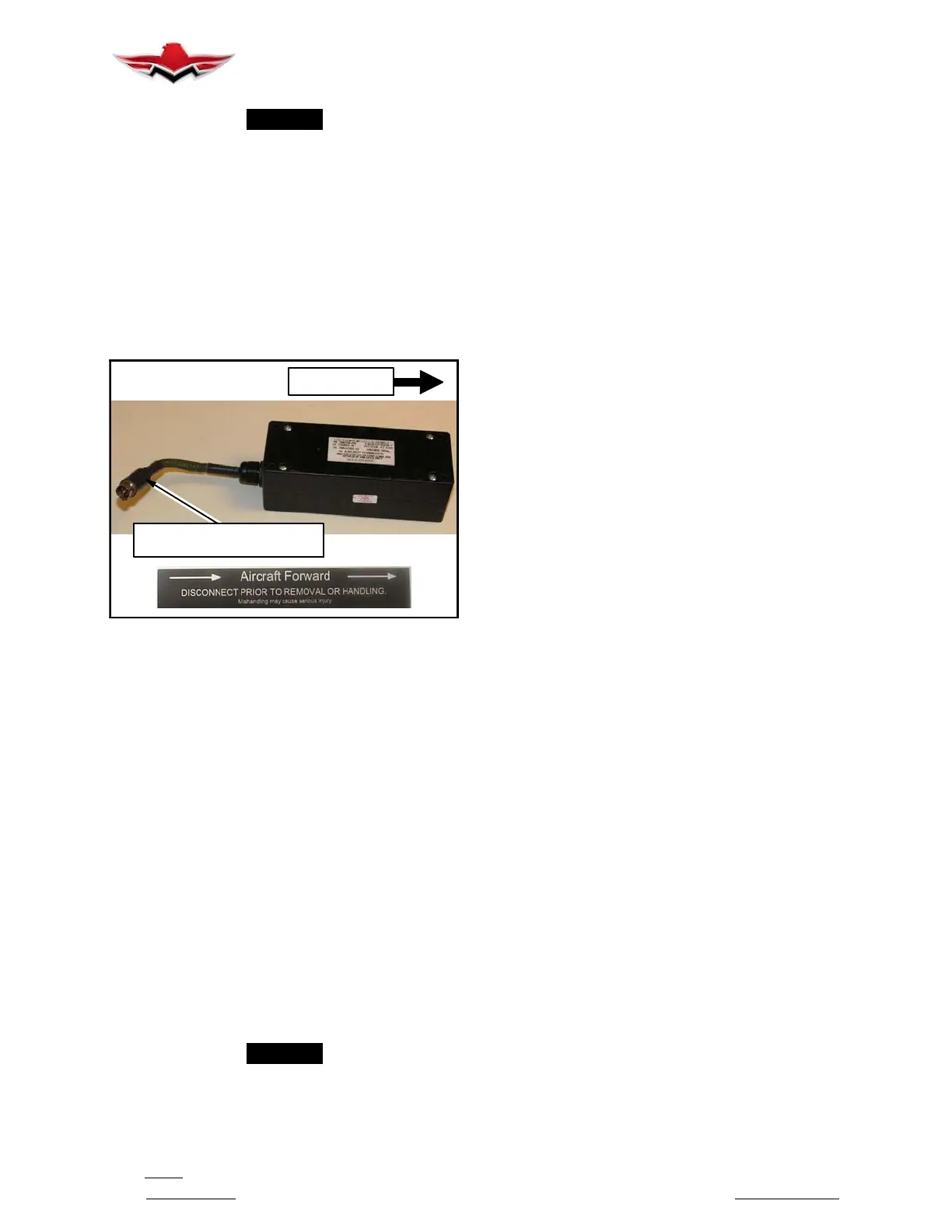
7. Insert EMA (50) into mounting hardware and secure
(for EMA installation hardware torque values, refer to
Mooney installation instructions/drawing 140345, Re-
straint Instl - Airbag, (for Aftermarket installations, Am-
Safe Installation drawings 509760 - pilot- co- pilot
seats or 509780 - passenger seats). The arrow on the
EMA label should face aircraft forward (see Figure
25- 6). Connect EMA to Cable Interface Assy’s EMA
connector. The connectors are keyed. Align connector
halves and seat fully until they lock.
AIRCRAFT
FORWARD
EMA PIGTAIL
TOWARD REAR OF AIRCRAFT
TYPICAL EMA AIRCRAFT FORWARD
INSTALLATION
FIGURE 25- 6
8. Connect End- Release Buckle Assembly to aircraft
structure or seat mounting point (for Aftermarket instal-
lations, refer to AmSafe Installation drawings 509760 -
pilot- co- pilot seats or 509780 - passenger seats).
9. Connect Cable Interface Assy(s)’ connector(s) to
SAA connector(s). Connect mated halves together in
proper orientation and slide Red Locking Tab forward to
locking position.
10. Secure Three- Point Airbag Belt(s) inertia reel or
manual adjustor connection point to aircraft structure.
Secure lap- belt to aircraft structure or seat mounting
point (for Aftermarket installations, refer to AmSafe
Installation drawings 509760 - pilot- co- pilot seats or
509780 - passenger seats).
11. Remove Safety Cable Tie from airbag buckle
tongue before performing functional testing.
12. Perform functional test on system (refer to V23 Sys-
tem Diagnostic To ol - Operation and Maintenance
Manual for testing procedures).
-NOTE-
It is required, after completion of functional test-
ing, to document t his task as an entry in the
aircraft’s logbook.
25-10-04 - CABIN LIGHTING
1. Reading Lights.
A momentary switch operates 4
overhead lamps in 3 m odes. Reading Light Switch
UP position, only the Pilot reading light is activated.
With Reading Light Switch in Down position, ALL
reading lights are activated. Passenger switches lo-
cated on each passenger’s arm rest (excluding front
seat passenger) can now activate On, Off or DIM in-
dividual reading lights. Front seat passenger’s light
switch is located forward of cabin door hinge on side
panel.
2. Dome Lights. ON or OFF switch operates 1 main
dome light in the center of upper console.
3. Glareshield and Panel Lights. A momentary light
switch UP position will illuminate full strength or
DOWN increases/decreases light intensity for the in-
strument panel area.
4. A 24 volt baggage compartment light is located in
the baggage compartment left hand headliner and is
controlled by a rocker switch mounted in the baggage
compartment right hand headliner assembly. Depress-
ing the rocker switch energizes a capacitor which in
turn energizes the fixture lamp. The duration that the
switch is depressed and held in the ON position will de-
termine the length of time the lamp remains illuminated.
This light will automatically turn OFF after approximate-
ly 10 minutes.
Refer to Chapter 33- 20- 00 for Interior Light mainte-
nanc
e procedures.
25-50-00 - BAGGAGE COMPARTMENT
The M20V baggage compartment, located aft of the
rear passenger seats, has a capacity of 20.9 cu. ft.
(0.59 cu. M) and a maximum allowable load of 120 lbs.
(54 Kg). Floor tiedown straps are provided (Refer to
“Seat Belts/Restraints” cleaning instructions outlined
above for Tiedown web and metal hardware cleaning
guidelines).
Additional cargo space (38.6 cu. ft./1.09 cu. M.) is avail-
able by removing rear seat, bottom cushion and seat
back cushion/cover and folding seat back down into
seat bottom frame. This can be accomplished by pull-
ing UP on the appropriate aft seat back reclining locking
handles located on the front of the spar.
A small storage area located aft of the top of the aft bag-
gage compartment bulkhead (hat rack) is restricted to
10 lbs. (4.5 Kg) capacity. This area will not be available
for storage if the optional air conditioning system is
installed in the aircraft.
The engine Hour Meter is located in the baggage
compartment rear panel.
25-60-00 - EMERGENCY EQUIPMENT
RT A1200 Fire Extinguisher: (if equipped)
A 2.6 lb. (Agent Weight) Dual- Halon (1211- 1301)
blend fire extinguisher is mounted, by metal spring
clamp, horizontally behind the pilot/co- pilot seat on the
main spar panel at floorboard level.
25-10-04
 Loading...


