MOONEY INTERNATIONAL CORPORATION
M20V SERVICE AND MAINTENANCE MANUAL
Page
Date
8
MAR 2017
Rev Date
H. Unclamp rudder pedals.
I. Adjust rudder stops (M) (Fig. 27−7), so that rud-
der travel is 23
°
(+1/−0 degrees) right and left.
J. After rudder stops (M) are set, rotate rudder
through full range of travel to assure solid contact with
stops and that nuts and bolt heads clear stop limiter (R).
Stop limiter (R) may be bent to obtain clearances and
contact with rudder stops (M) (Fig. 27−7).
-NOTE-
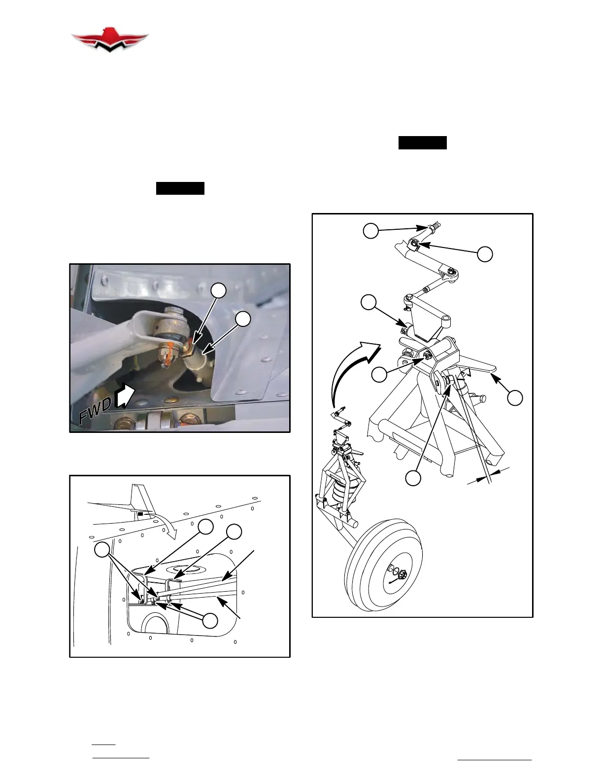
Nose Landing Gear steering stops (3) (Fig. 27−8),
should be adjusted so .020” clearance exists be-
tween adjustment stop (3) and gear truss assem-
bly (4) (Fig. 27−8) when rudder is at extreme left
and right travel position.
2
D
RUDDER HORN ADJUSTMENT
FIGURE 27−6
RUDDER
TUBE
ELEVATOR
TUBE
R
R
P
M
RUDDER & ELEVATOR STOP ADJUSTMENT
FIGURE 27−7
K. After setting stops, re−tighten all jam nuts, bolts
and secure; recheck all travel limits.
L. Center nose wheel by removing nut, washer and
bolt (1), (Fig. 27−8), and adjusting steering idler linkage
at (2). Bolts, nuts and washers (5) and (6) must be
installed, as s
hown, from rear to front. Refer to Section
32−50−00 for Nose Gear Steering and Tracking adjust-
ments.
-NOTE-
Measure rudder travel with travel board on rivet
line at station indicated on travel board GSE
030005, and with longitudinal trim (stabilizer) set
in the 0
o
position. Sta. 26.50 is located 3/4 in.
above skin splice on vertical fin.
USE .020 FEELER GAUGE
TO SET TURNING STOPS
.020
1
2
5
6
4
3
NOSE GEAR STEERING LINKAGE ADJUSTMENT
FIGURE 27−8
3. Allowable Free−Play Limits.
A. Vertical movement at rudder trailing edge − .08
inches.
(1) If excessive free−play exists, check the fol-
lowing areas for wear:
27-20-00



 To Next Page