MOONEY INTERNATIONAL CORPORATION
M20V SERVICE AND MAINTENANCE MANUAL
Page
Date
12
MAR 2017
Rev Date
C. Aileron−rudder interconnect system should be
rigged properly prior to rigging of rudder trim system.
(See Section 27−60−00)
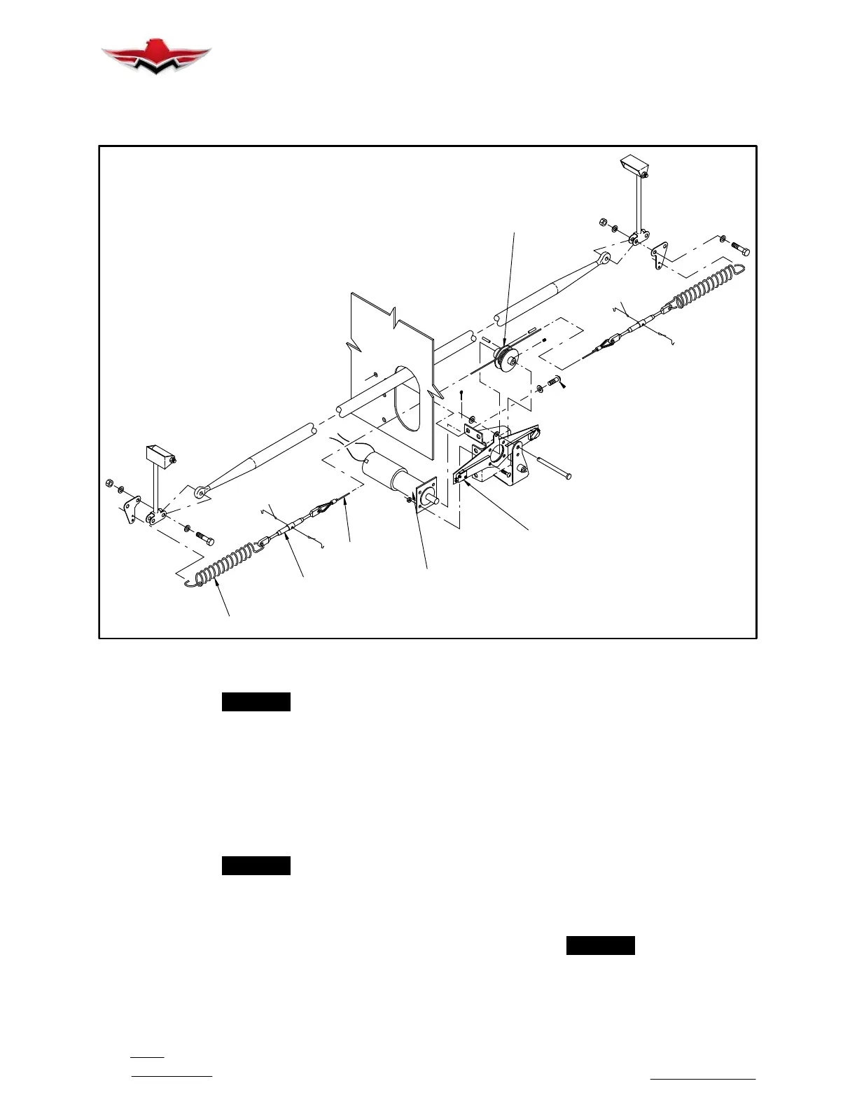
CAPSTAN
LIMIT SWITCH
ACTUATOR
CABLE
TURNBUCKLE
SPRING
RUDDER TRIM RIGGING
(Typical Hardware Layout Shown)
FIGURE 27−14
-NOTE-
Aileron−rudder interconnect system shall be dis-
connected from rudder system prior to rudder
trim rigging.
D. Deflect and lock rudder at 10
o
left position. Use
Rudder Travel Board GSE 0300005.
E. Remove tailcone battery access cover (left side)
and aft fiberglass belly panel to gain access to rudder
trim actuator assembly.
-NOTE-
The following steps are easier to accomplish if
the actuator assembly is removed from the air-
craft but they can be done while actuator is in its
normal operating location, if desired.
F. Electrically run actuator for left rudder deflection
(depress left sides of both RUDDER TRIM split
switches) until limit switch turns OFF actuator motor
(Aft limit switch is for LEFT rudder trim).
G. Wrap cable around capstan five full turns with
forward eye of cable ending up 12 inches from forward
circumference edge of capstan (See Fig. 27−14). Aft
end of cable will be in proper location for rigging proce-
dure. Temporarily secure cable/capstan position using
several wraps of suitable adhesive tape around cable
and capstan.
H. Extend and secure both springs to 9.8 inches in-
side measurement between hooks. Insert spring ex-
tender, P/N GSE 030035−501, end caps into spring
coils so that the 9.8 inch dimension is maintained.
Place spacer, P/N GSE 030035−005, over spring coils
and secure to −503 assembly with MS3367−1−9
straps. Two spring extenders, GSE 030035−503, are
required for rigging procedures.
-NOTE-
Rudder trim actuator assembly will need to be
re−installed at this time, if it was removed to ac-
complish the preceding steps.
27-40-02



 To Next Page