MOONEY INTERNATIONAL CORPORATION
M20V SERVICE AND MAINTENANCE MANUAL
Page
Date
11
MAR 2017
Rev Date
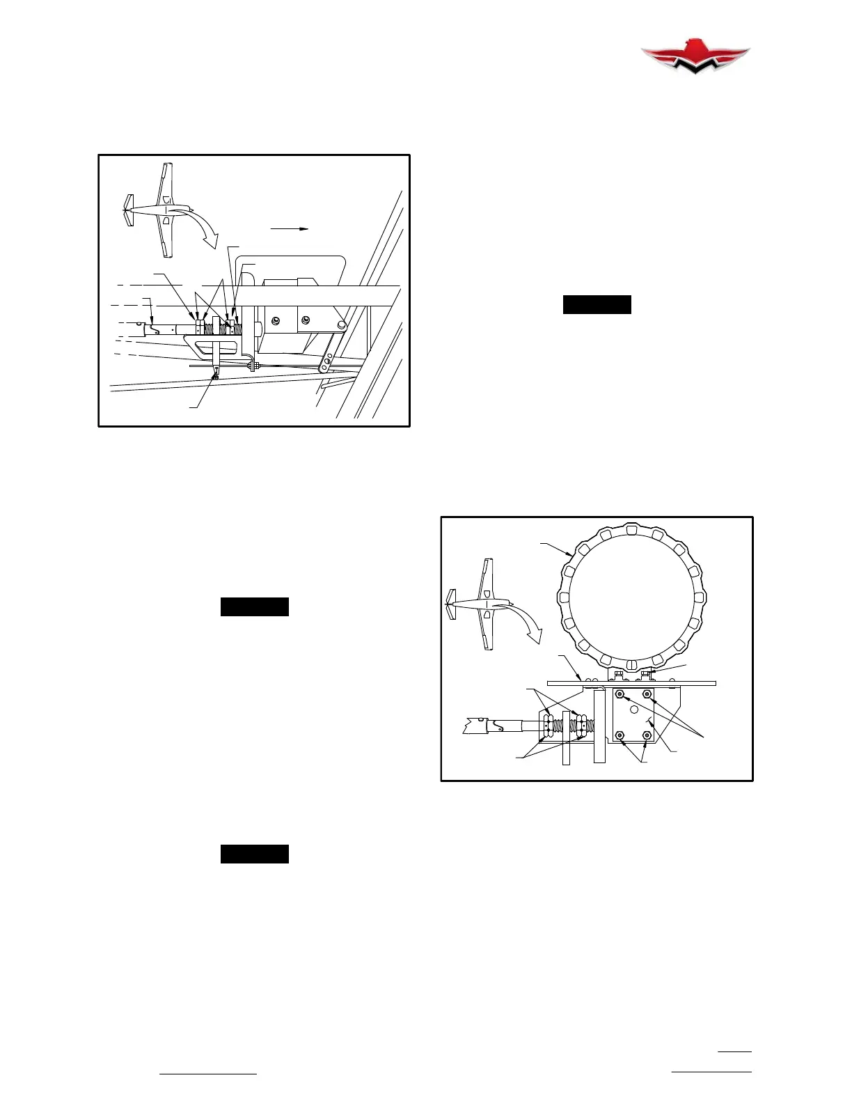
(C). Tighten setscrew and turn trim control wheel to full
NOSE DOWN position, trim screw nut (F) against stop
(A) or stepped nut (E).
DOWN
B
UP STOP
F
A
E
C
FWD
STOP
TRIM CONTROL ACTUATOR RIGGING
FIGURE 27−12
(2) Disconnect torque shaft (B) from trim screw
(C) (Fig. 27−12).
(3). Turn disconnected torque shaft (B) clock-
wise or counterclockwise until horizontal stabilizer as
measured, using the travel board, P/N 030004−503,
shown by Fig. 27−10, is within the following limits: +3.8
o
to +4.2
o
.
-NOTE-
Positive (+ degrees) stabilizer degrees mean that
stabilizer leading edge is moved up relative to
thrust line.
(4) Connect torque shaft (B) to trim screw (C)
(Fig. 27−12). NOSE DOWN stabilizer trim control rig-
ging is now complete.
B. Nose Up Stabilizer Trim Control Rigging and Ad-
justment.
(1). Loosen setscrew in stop or jamnut (A) (Fig.
27−12) and turn stop(s) on threaded shaft to move it to-
ward the trim screw gear box. Turn trim control wheel
toward NOSE UP position until horizontal stabilizer is
within the following limits: −6.5
o
to −7.0
o
.
-NOTE-
Negative stabilizer (− degrees) settings mean that
stabilizer leading edge is moved down relative to
thrust line.
(2) Rotate UP stop or stepped nut (E), (Fig.
27−12) clockwise or counterclockwise to make contact
with trim screw nut (F). Tighten setscrew. NOSE UP
stabilizer trim control rigging is now complete.
2. Stabilizer Trim Indicator − Rigging.
The indicator is connected to the trim control wheel as-
sembly to indicate stabilizer position relative to the air-
craft thrust line.
A. Adjust stabilizer trim to FULL DOWN position.
B. Adjust potentiometer, on trim wheel assembly,
per rigging instructions provided in the Garmin G1000
Maintenance Manual.
3. Stabilizer Free Play Limits.
A. Fore and aft movement at stabilizer tip − .12
inches.
B. Vertical movement at stabilizer tip − .10 inches.
-NOTE-
When removing trim screw from empennage, use
block of wood cut to fit opening between tailcone
and empennage, to prop empennage up when
trim screw is removed.
4. Stabilizer Trim Chain Adjustment. (Ref. Fig.
27−13).
A. With four mounting bolts (1) slack, adjust two
NAS428−3−4 bolts (2) to obtain maximum tension on
chain without causing binding.
B. Tighten four mounting bolts (1) after chain ten-
sion is adjusted.
WHEEL
ASSEMBLY
FLOORBOARD
STEPPED
STOP NUT
JAM NUT
GEAR BOX
ASSEMBLY
1
1
2
ELEVATOR TRIM CHAIN ADJUSTMENT
FIGURE 27−13
27-40-02 − RUDDER TRIM SYSTEM/RIGGING
1. Rudder Trim − Rigging
Rudder Trim consists of an electric actuator driving a
capstan/balancing bellcrank and spring system to com-
pensate for engine/propeller forces during long climbs
or takeoff power.
A. Aircraft should be flight tested and rigged for lat-
eral directional trim prior to final rigging of rudder trim
system.
B. Jack aircraft nose wheel off ground.
27-40-02


 To Next Page
 Loading...






