MOONEY INTERNATIONAL CORPORATION
M20V SERVICE AND MAINTENANCE MANUAL
Page
Date
10
MAR 2017
Rev Date
ing at rear tailcone bulkhead (C) (Fig. 27−5), if needed,
for clearance. Recheck elevator UP and DOWN travel.
I. Rotate elevator trim FULL UP to check that UP
stop (P) makes solid contact on stop limiter (R) (Fig.
27−7).
J. Re−tighten all jam nuts, attach bolts and secure
as necessary; recheck all control tube clearances and
travel limits.
27-30-03 − EMPENNAGE FREE PLAY LIMITS
Grasp Stinger (Empennage Assembly – not at control
surfaces) by hand and exert vertical and horizontal
movement to obtain desired dimensions. Measure
movement of the empennage assembly with tailcone at
tail skid. Allowable free play movement:
Horizontal Stabilizer at Tip:
0.12 inch max. – Fore and Aft
0.10 inch max. – Up & Down
Rudder at Lower Trailing Edge:
0.08 inch max. – Up & Down
C
L
DETAIL
”A”
A
N
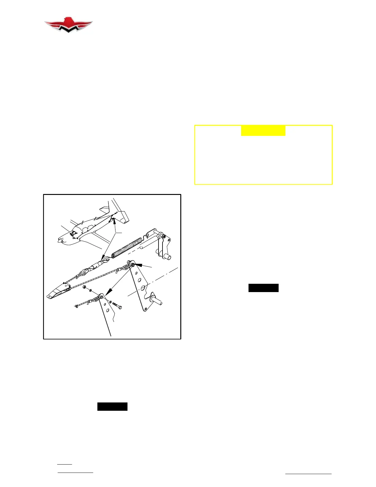
VARIABLE DOWNSPRING
FIGURE 27−11
27-31-00 − VARIABLE DOWNSPRING SYSTEM
A spring hooked into the elevator control system, in the
tailcone, refines the feel of the elevator in flight. A bell-
crank and cable tailors the spring tension appropriate
to the trimmed position of the stabilizer.
-NOTE-
Negative stabilizer (− degrees) settings mean that
stabilizer leading edge is moved down relative to
the thrust line.
1. Rigging − Variable Down Spring System
A. Set stabilizer at maximum positive (nose down)
setting and elevators full down. (Fig. 27−11).
B. Adjust turn buckle for a 14.0 to 16.0 in. lb. ten-
siometer reading on cable.
C. Check for positive clearance between cable end
and pulley sheave. Tensiometer reading should be 20
in. lb. maximum.
The hardware attaching the Down Spring Control
Cable Assembly to the Bellcrank must be assembled in
the proper orientation to the aircraft centerline (Fig.
27−11).
-CAUTION-
An incorrect hardware installation may cause
scoring of the Stabilizer Trim Torque Tube as a
result of the bolt thread contacting the Stabiliz-
er Trim Torque Tube surface during Horizontal
Stabilizer trimming movement. Scoring of the
Stabilizer Trim Torque Tube could result if at-
taching hardware is installed incorrectly.
The threaded end of the bolt (Fig. 27−11, Detail “A”)
should be inserted from aircraft left side to aircraft right
side; threaded end pointing in the outboard direction
away from the Stabilizer Trim Torque Tube (aircraft
centerline)
27-40-00 − TRIM SYSTEMS
27-40-01 −STABILIZER TRIM SYSTEM/RIGGING
To provide pitch trim control, the entire empennage piv-
ots around its main hinge points. The system consists
of a manually operated actuator (electrical operation
optional) that operates a series of torque tubes and uni-
versal joints connected to a jack screw on the aft tail-
cone bulkhead.
-NOTE-
A “stepped stop nut”, with a “jam nut” configura-
tion has been incorporated. This can be retro-
fitted to all M20V aircraft, if desired. This allows
trim screw nut (F) (Fig. 27−12) to contact stepped
portion of these two nuts and not bind.
1. Rigging − Stabilizer Trim System
The basic rigging, for either configuration, is identical to
procedures below except that stepped nut and jam nut
require being torqued together with two wrenches prior
to jam nut set screw (secure screw with Blue Loctite
#83−31 Grade C) being tightened against threaded
trim screw. Stepped nuts are required at the nose up
and the nose down positions facing trim screw nut (F)
(Fig. 27−12).
A. Nose Down Stabilizer Trim Control Rigging and
Adjustment.
(1) Loosen setscrew in stop/jamnut (A) (Fig.
27−12), break torque on jam nut/stepped nut (if
installed) and turn stop (A) or jam/stepped nut (A & E)
clockwise or counterclockwise to align aft edge of stop
or jam/stepped nut (A & E) with last thread of trimscrew
27-30-03


 To Next Page
 Loading...






