MOONEY INTERNATIONAL CORPORATION
M20V SERVICE AND MAINTENANCE MANUAL
Page
Date
17
MAR 2017
Rev Date
AILERONS
RUDDER
.070 MAX.
ALLOWABLE
DEFLECTION
.080 MAX. ALLOWABLE
DEFLECTION LEFT
OR RIGHT
TRAILING EDGE TRIMMING
FIGURE 27−20
A. Aileron. To correct for a left wing−heavy condi-
tion, bend right aileron trailing edge down; to correct for
a right wing−heavy condition, bend left aileron trailing
edge down − Keep within allowable deflection limits
(Fig 27−20) .
-NOTE-
Any deformed rivets must be replaced after trim-
ming aileron or rudder trailing edge.
B. Rudder. The rudder trailing edge may be
trimmed right or left as required.
C. Elevator. A full span tab is built into each eleva-
tor trailing edge and is fixed 7 degrees (+/−) ½ degree
trailing edge down. No further tolerance is allowed.
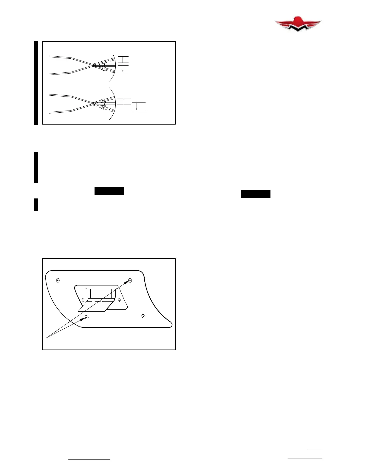
ADJUST UP TO ACTUATE SOONER
ADJUST DOWN TO ACTUATE LATER
ADJUSTMENT
SCREWS
DO NOT BEND VANE
IT MAY BREAK
STALL SWITCH ADJUSTMENT
FIGURE 27−21
27-95-00 − STALL WARNING – MAINTENANCE
PRACTICES
1. Stall Warning Switch Removal.
A. Remove screws or rivets attaching access cov-
er aft of stall warning switch on lower wing surface.
B. Remove the two adjustment screws which hold
switch to wing leading edge.
C. Disconnect the two wires from switch.
2. Stall Warning Switch Installation.
A. Connect electrical wires to switch.
B. Position switch in opening of lower wing leading
edge; install the two adjustment screws.
C. Replace access cover securely.
D. Adjust switch. See STALL WARNING INDICA-
TION SYSTEM ADJUSTMENT below.
3. Stall Warning Indicating System Adjustment (Fig.
27−21).
The stall warning switch is adjusted when the airplane
is test flown at the factory. Should it require readjusting,
proceed as follows:
A. Locate switch installation on under surface of
left wing leading edge and loosen the two phillips head
screws, one on either side of the vane.
B. If stall warning has been activating too early, pull
vane BACK and DOWN.
-NOTE-
NEVER TRY TO ADJUST SWITCH BY BENDING
VANE. This part has been heat treated and can-
not be bent without damaging or breaking vane
or switch.
C. If stall warning has been activating too late,
push vane UP and FORWARD. Moving vane, with the
phillips head screws loosened, moves entire unit up or
down inside wing, causing switch to be closed earlier or
later. Re−tighten screws after making each adjustment.
As a rule of thumb, moving vane tip 1/4 inch will change
the time the stall warning actuates by about 5 KTS indi-
cated air speed.
The only way to test the accuracy of the setting is to fly
airplane into a stall, noting speed at which the Sonalert
tone is heard and approximately one second later
“STALL” is annunciated over the speaker.
The stall must be made in various configurations,
clean, gear and flaps down and power on and power
off. It may be necessary to make several alternate ad-
justments and test flights before the desired setting can
be reached.
The stall warning should actuate at no less than 5 KTS.
nor more than 10 KTS. preceding the stall and shall
continue until stall occurs in power off configuration.
The rate of speed reduction shall not exceed one knot
per second with airplane trimmed to 1.5 times stall
speed.
The switch setting should be checked and adjusted as
necessary whenever a wing or wing leading edge is re-
placed or extensively repaired or if a new switch is
installed. The switch should require no adjustment in
normal service.
OCT 2017
27-95-00


 To Next Page
 Loading...






