MOONEY INTERNATIONAL CORPORATION
M20V SERVICE AND MAINTENANCE MANUAL
Page
Date
16
MAR 2017
Rev Date
7.25”
SCREW
SPRING
FUSELAGE
BLKHD.
CONTROL
BRACKET
RUDDER
CONTROL
TUBE
BELLCRANK
ASSY
TRUSS
TUBE
STOP
SCREW
ASSY.
SCREW
SPRING
STOP
OUTBD
FWD
VIEW LOOKING UP
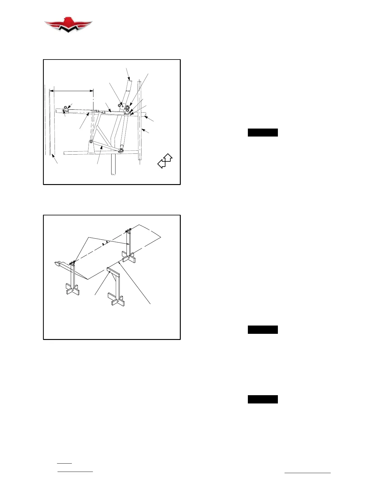
AILERON/RUDDER INTERCONNECT
FIGURE 27−18
KNIFE EDGE
SUPPORT
TRAILING EDGE
RESTING SUPPORT
(OPTIONAL)
USE LIGHT WEIGHT PUSH/PULL
FISH SCALE AT TRAILING EDGE
TO DETERMINE IF BALANCE OF
CONTROL SURFACE IS CORRECT
CONTROL SURFACE STATIC BALANCE
DIAGRAM
FIGURE 27−19
27-92-00 − BALANCING EQUIPMENT − STATIC
The design of the balancing fixture is not critical provid-
ing the requirements of this section are met.
1. Obtain or otherwise fabricate two (2) knife edge
and supports approximately one (1) foot in height such
that they can be placed on a table and be stabilized to
prevent tipping (See Fig. 27−19). The knife edge hinge
supports MUST be LEVEL and PERPENDICULAR to
the hinge axis of the control surface.
2. Weight Scales: Scales used to record weights
must be accurate within 0.02 lbs or 1/2 oz.
27-93-00 − BALANCING PROCEDURE
27-93-01 − DETAIL PROCEDURES – STATIC BAL-
ANCING
1. A line drawn through the hinge line support points
must be level and perpendicular to the supporting knife
edges.
2. The supporting knife edges must be horizontal and
parallel to each other within the requirements of Step 1
above.
-NOTE-
Ailerons are balanced up−side down on knife
edge supports.
3. Elevators and rudders are balanced with the ”Con-
trol Horn” pointing upward.
4. All control surfaces are balanced with the hinge
center line and the tip rib chord line level. Two tooling
holes are located in the tip ribs and are on the rib chord
line (rib center line). Chordwise level can be obtained
by using a spirit level and pins inserted into these tool-
ing holes (Fig. 27−17).
5. Install a 1/4 inch bolt or pin through the inboard and
outboard AILERON hinge bracket. Install a No. 10 bolt
or pin through inboard and outboard ELEVATOR hinge
bearing, and top and bottom RUDDER hinge bearing.
6. Position and level the control surface on the knife
edge hinge supports.
7. Accurately measure control surface load (weight),
using accurate push/pull scale, at a measured distance
(arm) from the hinge axis centerline to AFT control sur-
face rivet line. Measurements should be taken in a draft
free environment. Calculate the moment (arm times
weight) and compare the results with “Balance Moment
Limits” indicated in Fig. 27−17.
8. Control surfaces MUST BE RECHECKED for bal-
ance after any painting, stripping, repair or alteration.
-NOTE-
If specified moments cannot be met (reference
Fig. 27−18), heavier balance weights can be ob-
tained through a Mooney Service Center. This
approach should be examined before reworking
any repair or restripping and repainting the af-
fected control surface. A lighter weight can be
produced by shaving existing balance weight.
27-94-00 − CONTROL SURFACE TRAILING EDGE
-NOTE-
Verify flight control rigging is correct before
bending trailing edge.
1. Trimming. A special pair of wide nose vice grip pli-
ers are to be used to bend the trailing edges as neces-
sary (See Fig. 27−20).
27-92-00


 To Next Page
 Loading...






