MOONEY INTERNATIONAL CORPORATION
M20V SERVICE AND MAINTENANCE MANUAL
Page
Date
15
MAR 2017
Rev Date
D. Adjust switch stack until Bottom Micro−Switch
just opens.
E. Top switch will be automatically adjusted.
F. Cycle flaps UP, TAKEOFF & DOWN; verify prop-
er settings at TAKEOFF when Flaps are traveling down
from full up position.
3. Wing Flap Indicator – Rigging
A. Adjust flap potentiometer (8) (Fig. 27−15) on air-
craft per Garmin G1000 Line Maintenance and Config-
uration Manual instructions for Flaps and Trim Rigging
instrument calibration.
SURFACE DESCRIPTION AIRCRAFT EFFECTIVITY BALANCING MOMENT LIMITS
430026−507 & −508
ELEVATOR
33−0001 THRU 33−TBA UNDERBALANCE
11.00 In. Lbs. TO 8.50 In. Lbs.
460043−513
RUDDER
33−0001 THRU 33−TBA OVERBALANCE −8.00 In. Lbs. TO
AN OVERBALANCE −1.00 In. Lbs.
230015−509 & −510
AILERON
33−0001 THRU 33−TBA UNDERBALANCE 1.40 In. Lbs.
TO
AN OVERBALANCE −2.0 In. Lbs.
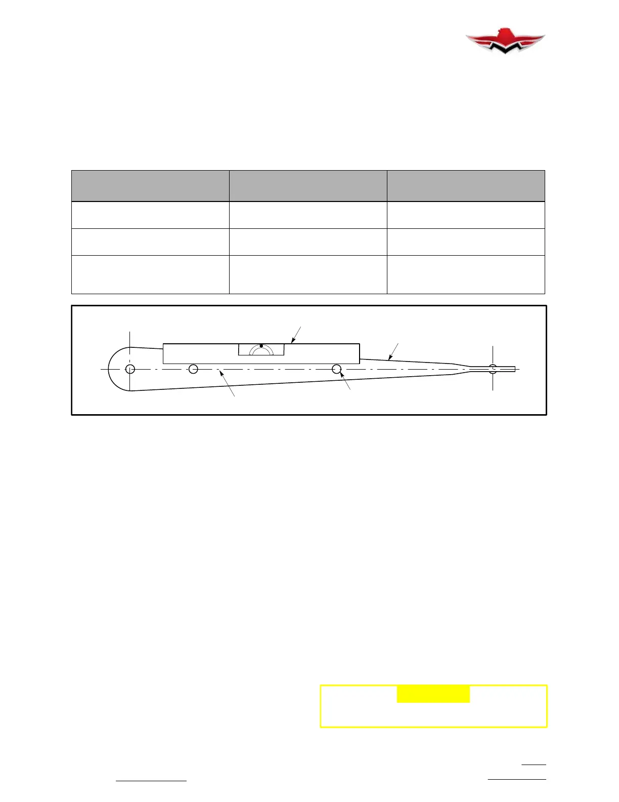
SPIRIT LEVEL
CENTERLINE
HINGE
AFT
RIVET LINE
LEVEL
CHORDLINE
TOOLING HOLES (2)
CONTROL
SURFACE
WITH PINS INSERTED
CONTROL SURFACE BALANCE LIMITS
FIGURE 27−17
27-60-00 − AILERON/RUDDER INTERCONNECT
SYSTEM
The aileron/rudder interconnect system assists in coor-
dinated maneuvers and reduction of adverse yaw dur-
ing turns. The system is connected through springs to
allow override of either control movement when input
separately.
1. Aileron/Rudder Interconnect System – Rigging
(Fig. 27−18)
A. With controls in neutral position, locate bracket,
on center aileron control tube, so that the end of bell-
crank assembly will be 7.25 inch AFT of fuselage bulk-
head.
B. Holding both rudder and aileron controls in neu-
tral position, install springs on bellcrank and stops.
Position stops on rudder control tube so that installed
length of each spring is 4.90 inch.
C. Clamp stops and brackets in place. Drill through
stop, bracket and into control tube for AN530−4R6 PK
screws. Make sure PK screws are in place to secure all
three brackets.
Refer to Garmin G1000 Line Maintenance and Config-
uration Manual for Rudder Trim adjustment/calibration
procedures.
27-90-00 − MISCELLANEOUS
27-91-00 − CONTROL SURFACE STATIC BAL-
ANCING
Control surface balance must be checked when control
surfaces is repaired, altered or repainted. It is recom-
mended that control surfaces be stripped prior to re-
painting. The control surface balance limits shown in
chart below and Figure 27−17 apply to a completed,
painted control surface only. Complete control surfaces
include (as applicable) balance weight, control attach-
ment horn and attaching hardware, static wicks (when
installed as optional equipment), and rudder taillight
and/or strobe light assembly installed.
Control surfaces must be rebalanced in accordance
with the proc
edures in Section 27−93−00.
-CAUTION-
All control surfaces should be stripped prior
to repainting.
27-60-00


 To Next Page
 Loading...






