MOONEY INTERNATIONAL CORPORATION
M20V SERVICE AND MAINTENANCE MANUAL
Page
Date
14
MAR 2017
Rev Date
7. Place torque tube/pitch trim servo assembly on
work bench for removal and replacement of bearing
block.
8. Follow Pitch trim System vendor instructions for
bearing block replacement.
9. Reinstall torque tube/pitch trim servo assembly
into tailcone.
10. After reinstallation and reconnection of all com-
ponents, electrical and mechanical, it will be essential
to check stabilizer pitch trim system rigging in accor-
dance with Sec
tion 27−40−01. Recalibration of the
Garmin system programs must be performed per Gar-
min System Maintenance Manual.
1
2
3
4
5
6
7
8
9
1
2
9
4
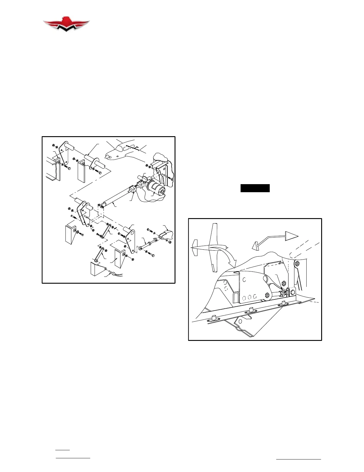
FLAP ACTUATOR ASSEMBLY & INSTALLATION
FIGURE 27−15
27-50-00 − WING FLAP SYSTEM
Push−pull tubes and bellcranks interconnect the flaps.
The flaps are operated by an electrical motor driven ac-
tuator (1) connected to a jack shaft (2). The jack shaft is
connected to an actuator bracket (3) (Fig. 27−15) on
each flap just outboard of jack shaft hinges (4) by a
push−pull rod end bearing (5) and hardware. Each flap
pivots about four hinges. Travel is controlled by limit
switches (6) and (7) and UP stops located at each out-
board flap hinge.
Flap position is indicated in the cockpit through an elec-
trical potentiometer system (8) connected to the jack
shaft actuator horn (9).
Lubric
ate the actuator gear box and ball screw at
inter-vals with lubricants prescribed in CHAPTER 5.
The flap system incorporates a preselect feature which
allows flaps to be activated as desired, UP, TAKEOFF
or DOWN.
The flap switch is located on center console. Flap posi-
tion is indicated on the Garmin G1000 Engine/Airframe
Indicator display screen. The flaps can be retracted
completely by placing the switch in the UP position or to
any preselect setting.
Refer to the Garmin G1000 Line Maintenance and
Configuration Manual for Rigging adjustments and in-
strument calibration.
1. Wing Flap Removal and Installation.
A. Remove wing flap hinge fairing to expose flap
push−pull tube.
B. Remove bolt, nut, and washer from flap−actuat-
ing attachment.
C. Remove bolts, nuts and washers at flap hinge
points.
D. Remove flap by pulling down and aft.
E. Install wing flaps in reverse sequence of remov-
al. Recheck security and safety of attaching bolts.
2. Wing Flap Rigging and Adjustment.
-NOTE-
Flap deflections are to be measured with travel
board GSE030003 at station indicated on travel
board. (See Section 27−20−00, Fig. 27−8)
LEFT
FWD
1
WING FLAP ADJUSTMENT
FIGURE 27−16
A. Adjust right and left inboard linkage at rod end
bearing (1), (Fig. 27−16) to obtain a flap deflection of
33
o
(+0
o
/−2
o
). Retract flaps to 0
o
(+/−2
o
); set flap out-
board travel “UP” stops (not illustrated) so that flaps
align with ailerons in neutral position.
B. The limit switches 6 & 7, (Fig. 27−15) should be
adjusted so that under flight loads the actuator overrun
will not allow the flaps to exceed either UP or DOWN
positions.
C. Extend flaps to TAKEOFF position (10
o
+/−1
o
).
27-50-00


 To Next Page
 Loading...






