MOONEY INTERNATIONAL CORPORATION
M20V SERVICE AND MAINTENANCE MANUAL
Date
MAR 2017
Rev Date
Page
7
The airspeed tape is a vertical scale along the left mar-
gin of the display. The current airspeed is always in the
middle of the tape and indicated by the triangular point-
er on the left side of the airspeed window. The tape has
numeric indications every ten (10) or twenty (20) units
depending on the unit type selected. Minor graduations
appear every five (5) or ten (10) units, respectively. In
horizontal installations, the tape spans approximately
50 or 100 units from top to bottom and in vertical install-
ations; the tape spans approximately 80 or 160 units
from top to bottom depending on unit type. The tape will
“roll” or scroll to assist in quick reference as to the in-
creasing or decreasing nature of the aircraft’s airspeed.
The airspeed limitations, also known as “V- speeds”,
are indicated with colored range marking bands placed
vertically along the left margin next to the airspeed
tape. The colors and values of each bar can be set dur-
ing installation in Configuration Mode. Colors should be
selected based on industry- defined colors and
V- speed limits as defined by the aircraft’s specific Pi-
lot’s Operating Handbook (POH). Range markings can
be represented by full- width bars, half- width bars and/
or radial marks. A traditional “barber pole” may also be
displayed if the aircraft requires and provides, the ap-
propriate Vmo and/ or Mmo values.
G1000 AIRSPEED DISPLAY
The Garmin G1000 PFD displays airspeed on a rolling
number gauge using an LCD screen “moving tape” dis-
play. The following information is also displayed:
Speed indication
Speed ranges
Airspeed trend vector
Vspeed references
The numeric labels and major tick marks on the moving
tape are marked at intervals of 10 knots, while minor
tick marks on the moving tape are indicated at intervals
of 5 knots. Speed indication starts at 20 knots, with 60
knots of airspeed viewable at any given time. The actu-
al airspeed is displayed inside a black pointer. The
pointer remains black until reaching never exceed
speed (Vne), at which point it turns red.
Speed Ranges
A color coded (white, green, yellow, and red) speed
range strip is located on the moving tape. The colors
denote:
Flaps Operating Range – 59- 110 KIAS
Normal Operating Range - 66- 173 KIAS
Caution Range – 174- 194 KIAS
Never Exceed Speed (Vne) - 194 KIAS
A red range is also present for low speed awareness.
Refer to the Aircraft Flight Manual Supplement (AFMS)
for speed criteria.
Refer to Garmin G1000 Line Maintenance and Config-
uration Manual for service and troubleshooting infor-
mation.
-NOTE-
See Section 27-95-00 for stall warning systems.
34-12-00 - VERTICAL SPEED INDICATOR
The Garmin GDC 74A provides digital air data com-
putations (including Vertical Speed) to the G1000 sys-
tem. The unit is mounted behind the PFD. Power is re-
ceived from the “Essential” buss. The GDC 74A
connects to existing Pitot/static ports and converts
barometric pressure changes within the static port lines
to aircraft ascent or descent rate.
The PFD Vertical Speed Indicator displays the aircraft
vertical speed with numeric labels and tick marks at
1,000 ft. and 2,000 ft. in each direction. Minor tick
marks are at intervals of 500 ft.
Refer to G1000 Line Maintenance and Configuration
Manual for service and troubleshooting information.
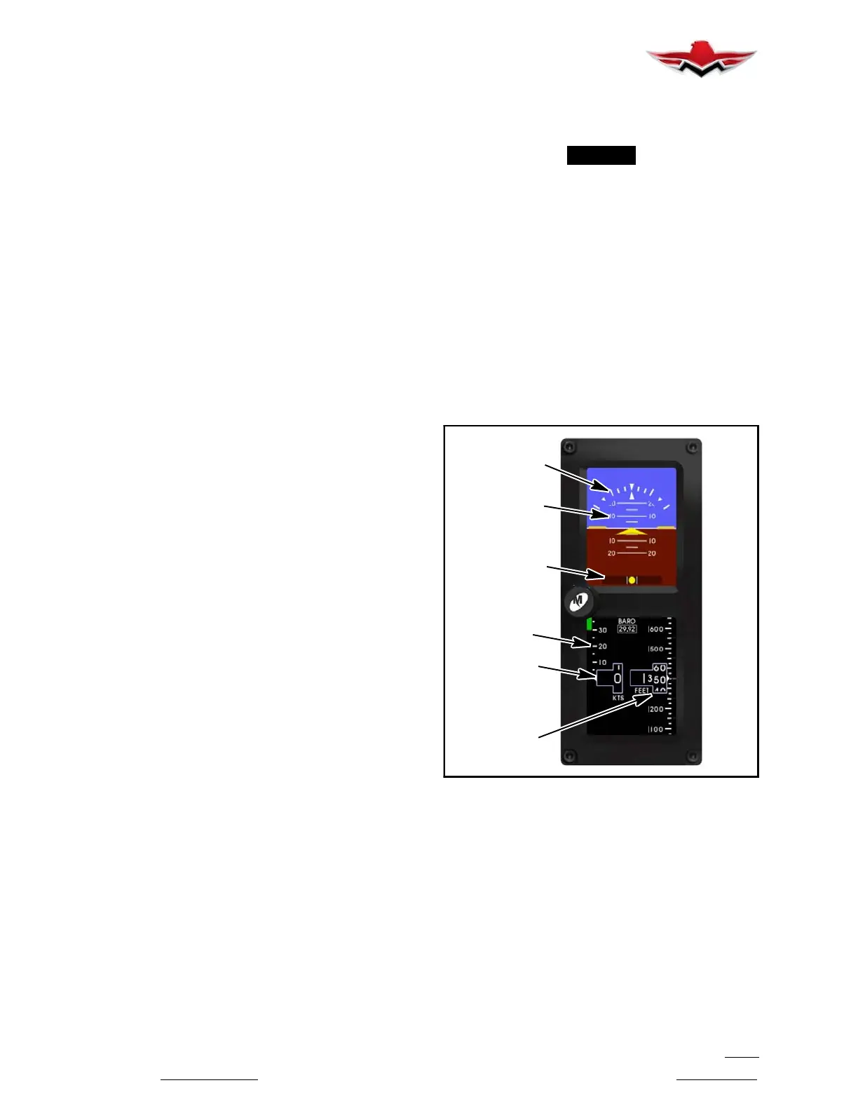
ROLL/BANK
SCALE
PITCH
SCALE
SLIP
AIRSPEED
WINDOW
ALTITUDE
WINDOW
AIRSPEED
TAPE
INDICATOR
STANDBY ATTITUDE MODULE (SAM)
FIGURE 34-2
34-13-00 - ALTIMETER
STANDBY ATTITUDE MODULE (SAM)
ALTIMETER DISPLAY
The altimeter or altitude portion of the SAM display will
always appear on the right side of the right display
when mounted horizontally and on the right side of the
bottom display when mounted vertically. An example of
the altitude display is shown in Figure 34-2.
The altimeter consists of four parts: the altitude win-
dow, the altitude tape, the barometer window, and the
optional altitude trend bar.
34-12-00
 Loading...


