MOONEY INTERNATIONAL CORPORATION
M20V SERVICE AND MAINTENANCE MANUAL
Page
Date
17
MAR 2017
Rev Date
C. Countersink dimple hole in skin allowing coun-
tersink to extend into substructure.
D. Install conical washer, use next oversize rivet
size. Wet prime washer and adjacent skin and doubler
surfaces prior to assembly (Figure 51- 19).
E. Drill remainder of hole to allow installation of
next larger diameter rivet than rivets in original pattern.
SUBSTRUCTURE
NEXT OVERSIZE RIVET
100 CONICAL WASHER
SCARF EDGES
WET PRIMER
O
DOUBLER
SKIN
OVERSIZE HOLE
FIGURE 51- 19
51-14-00 - HORIZONTAL STABILIZER & VER-
TICAL FIN REPAIR
51-14-01 - LEADING EDGE SKIN REPAIR
The horizontal stabilizer and vertical fin leading edge
interiors are inaccessible near the tailcone. To repair
damage in these areas, cut a standard (3.0 inches by
6.5 inches) access hole in lower side of stabilizer lead-
ing edge and close access hole by installing inspection
cover P/N 913000- 501.
51-14-02 - MAIN SPAR REPAIR OUTBOARD OF
STA. 9.00
Repair damage to horizontal stabilizer main spar by
straightening damaged area and inspecting it carefully
for cracks. If cracks are formed, stop drill or remove
cracked area.
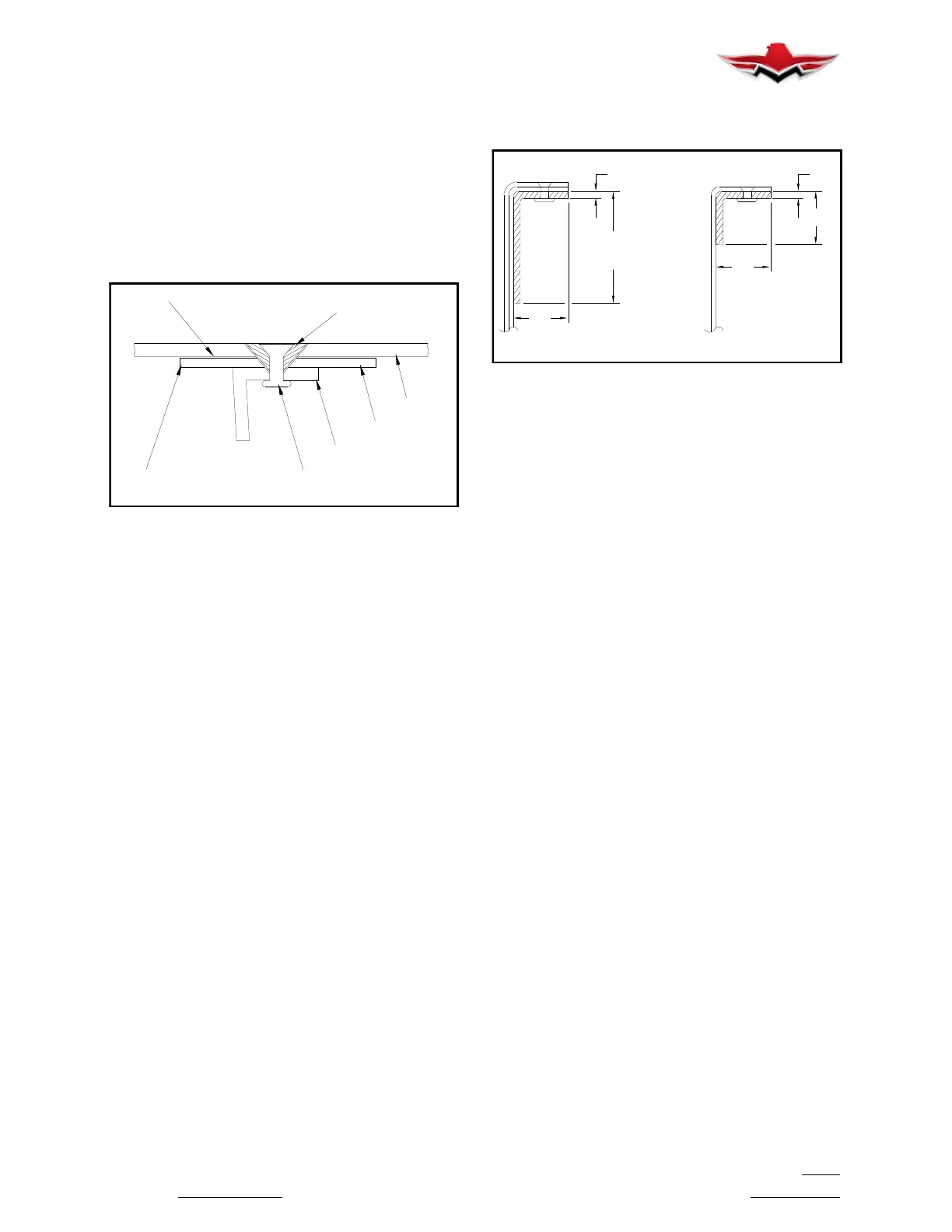
1. Repair damage between STA 9.00 and STA 34.0
(Figure 51- 20) on spar upper flange, and between STA
9.00 and STA 40.0 on spar lower flange with a splice
angle formed from .070 AISI 4130 steel, condition N.
The splice angle flanges must be as wide as original
spar flanges. The splice angle must be long enough to
install 11 AD4 rivets through skin and 11 rivets through
spar web on each side of damaged area.
Prime splice angle before riveting it to spar. Pick up five
existing rivet holes and drill six new holes between ex-
isting rivet holes in the skin at each side of the damaged
area. Install 22 AD4 rivets through splice angle and
skin, and 22 AD4 rivets through splice angle and spar
web.
.70
.75
ANGLE BEING SPLICED
SAME LENGTH AS
.75
.070 .050
SPAR REPAIR (SAT. 9.0 & OUTBD.)
FIGURE 51- 20
2. Repair main spar cap damage between STA 34
and STA 48.5 by forming a splice angle from 3/4 inch by
3/4 inch .050 2024- T3 sheet aluminum (Figure 51- 20).
Pick up five existing holes and drill six new rivet holes
between existing holes in the skin on each side of dam-
aged area. Install 11 AD4 rivets through angle and skin
and 10 AD4 rivets through angle and web on each side
of the damaged area.
3. Repair main spar damage from STA 48.5 outboard
by installing splice angles made from .040 2024- T3
material on both side of web using 12 AD4 rivets (6
through skin and 6 through web on each side of dam-
aged area) (Figure 51- 21).
Pick up three existing holes and drill three new holes
between existing holes on each side of damaged area.
4. Repair main spar web damage outboard of STA
34.0, top flange, and STA 48.5, lower flange by forming
a splice angle from .050 2024- T3 aluminum (Figure
51- 22). The splice angle web flange should be cut to
allow sufficient coverage of the damaged area of exist-
ing web and long enough to install 6 AD4 rivets on the
flange on each side of the damaged area. Pick up 3 ex-
isting rivet holes on flange of spar and drill 3 new rivet
holes between existing holes. Drill 10 rivet holes
through splice angle and web on each side of the dam-
aged web area. The damaged web should be stop
drilled or cracked area removed prior to splice angle
installation. Prime splice angle and debur spar web and
flange before installing splice.
5. Spar webs outboard of STA 48.5 cracked more
than 50% of the web height may be repaired (see Fig-
ure 51- 23). Form a splice plate from .050 2024- T3 alu-
minum to fit the inside dimensions of the web and
flange at the damaged area. Pick up 3 existing rivet
holes on top and bottom flange on each side of dam-
aged area and drill 2 new AD4 rivet holes between
these existing holes. Pick up all rivet holes on web un-
der splice plate and drill new rivet holes on equal spac-
ing around the damaged area similar to that on Figure
51- 18 rivets on each side of damaged area.
51-14-00
 Loading...


