MOONEY INTERNATIONAL CORPORATION
M20V SERVICE AND MAINTENANCE MANUAL
Date
MAR 2017
Rev Date
Page
8
INSTALLATION:
A. If not installed, locate and bond actuator magnet
approximately 1.5” .5” from upper door latch opening
in door shell with Click Bond CB200 adhesive as shown
in Figure 52- 3. Follow manufacturer’s instructions for
surface prep, application, and cure time.
B. Install upper guide pin in door shell, with (2) retain-
ing screws, tighten securely.
C. Locate and bond outer cabin door handle to door
shell with Hysol EA9394 adhesive. Install (3) cherry
max rivets to provide clamp force while adhesive cures.
Follow manufacturer’s instructions for surface prep,
application, and cure time. Wipe any excess adhesive
that is squeezed out, see Figure 52- 2
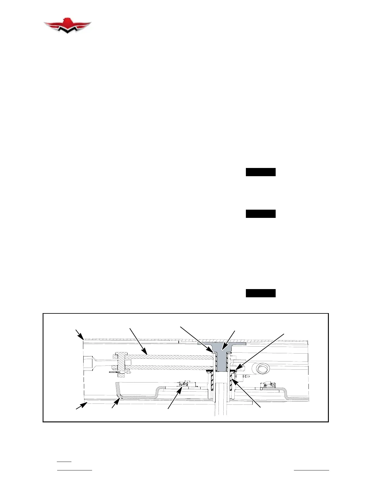
D. Locate bonded aluminum button on interior cabin
door handle area, install (1) small flanged bushing, (1)
bellcrank, (1) washer and (1) large flanged bushing,
see orientation of parts in Figure 52- 4.
E. Install cabin door handle cover plate, with (3)
screws and (3) washers, tighten securely.
F. Install upper door latch, with (2) retaining bolts and
anchor plate(s), tighten securely.
G. Install (2) control cable mounting brackets, with
(2) screws on each mounting bracket, tighten securely.
H. Install Control cable into door assembly, referen-
cing the correct orientation as removed (Upper or
Lower).
I. Connect the upper and lower door latch control
yoke ends, and install removed clevis pins, washers
and new cotter keys.
J. Carefully Install lower door link with latching pin
and spring into position (bevel of door latching pin faces
outward) - slide removed clevis pin into position on
bellcrank, install washer and new cotter key.
K. Install upper door link and secure with removed
clevis pins, washers and new cotter pins, on both sides
of link assembly.
52-10-05 - CABIN DOOR RIGGING/ADJUSTMENT
PROCEDURES
The cabin door latching mechanism has several adjust-
ment points that may be utilized to obtain proper rigging
(Figure 52- 2). Removal of interior door panel will be re-
quired to gain access to adjustment points.
1. Adjust cabin door linkage to satisfy requirements
listed below.
A. Latching pin must contact striker plate hole on
door frame, the full circumference of pin, when mecha-
nism is in full latched position.
B. Latching pin must clear striker plate when open-
ing or closing door with latching mechanism in full open
or closed position.
C. As lower link (1) and bellcrank arm (2), (Fig.
52- 2) travel over center, the spring (3), is to be com-
pressed to 1.000” +/- .030”
-NOTE-
Washers may be added to shim as required.
D. The lower link (1) and bellcrank arm (2), in full
locked position, should be overcenter a minimum of .3
inches, (Figure 52- 2).
-NOTE-
It is not necessary that lower link contact upper
link, (Figure 52- 2).
E. The outside handle is to be flush with outside
skin when mechanism is in full locked position.
F. In full locked position, upper latch jaws must be
closed and latch slide cam at the end of its full locked
travel. See adjustment points, (Figure 52- 2).
G. In full open position, upper latch jaws must be
open and slide cam at end of its full travel.
-NOTE-
Slide cam moves 1.13 in. from full locked to full
open position.
INTERIOR DOOR
LATCH SHAFT
(BONDED)
SMALL FLANGED
BUSHING
LARGE FLANGED
BUSHING
WASHER
COVER
COVER PLATE
MOUNTING SCREWS (3)
BELLCRANK
REF: OUTER DOOR
REF: INNER
DOOR PANEL
PLATE
PANEL
CABIN DOORS ATTACHING HARDWARE
FIGURE 52- 4
52-10-05
 Loading...


