MOONEY INTERNATIONAL C ORPORATION
M20V SERVICE AND MAINTENANCE MANUAL
Date
MAR 2017
Rev Date
Page
8
57-20-00 - AUXILIARY STRUCTURES
57-20-01 - JACK POINTS
Wing jack points are located on LH & RH lower wing.
The threaded wing tie down eyebolt fittings are de-
s
igned to accept non- threaded jack points. These are
located outboard of each main gear. The nose jack
point is located aft of left hand cowl flap at Fus. Sta.
- 5.51. See Section 7-10-00 for complete jacking proce-
dures.
WS 103.5
1
2
3
4
4
4
1
5
WS 118.25
WS 133.0
WS 147.75
WS 163.0
WS 178.25
WS 193.5
WS 210.97
WS 24.5
WS 43.5
WS 59.25
WS 74.0
WS 88.75
WS 103.5
WS 118.25
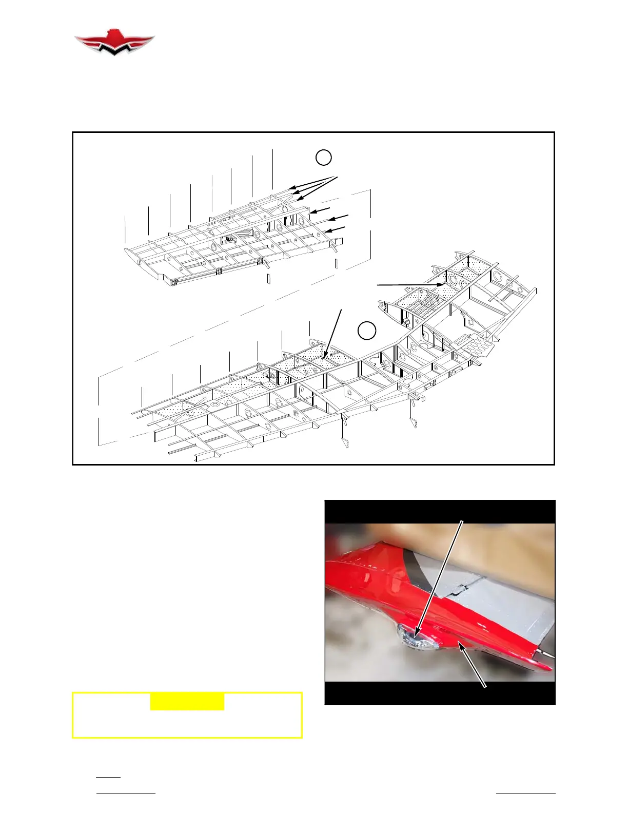
WING STRUCTURE
FIGURE 57-3
57-20-02 - WING TIPS
The M20V wing tips are non- structural, fiberglass com-
ponents. They are riveted to upper and lower wing
skins during final assembly of wing structure (Figure
57- 4).
1. Wing tip removal.
A. Remove navigation/strobe light assembly per
instructions in Chapter 33-41-03.
B. Drill out rivets holding tip to upper and lower
wing skin. Remove all rivet shanks with a punch.
C. Carefully pull wing tip away from wing rib and
skins.
2. Wing tip installation.
A. Place new or repaired wing tip in place.
-CAUTION-
Be sure aileron and aileron balance weights are
not restricted in movement, either direction.
NAVIGATION/STROBE
LIGHT ASSY.
WING TIP
WING TIP ASSEMBLY
FIGURE 57-4
57-20-00
 Loading...


