MOONEY INTERNATIONAL CORPORATION
M20V SERVICE AND MAINTENANCE MANUAL
Date
MAR 2017
Rev Date
Page
5
77-00-00 - GENERAL
Engine indicating instruments and their sending units,
transducers, probes, etc., must be operating properly
to prevent engine damage.The G1000 displays the in-
formation on the display screen (Fig 77- 1).
It is recommended that all engine indicating compo-
nents be checked at each 100 hour or annual inspec-
tion to verify proper operation. Calibrated instruments
may be “Tee’d” into particular systems for comparison
checks between them and aircraft instruments.
77-00-01 - RANGES
Powerplant instruments operate electrically through
variations in resistance caused by pressure or temper-
ature changes, by variations in current output caused
by varying engine RPM or alternator output, or by pres-
sure from engine induction system.
77-10-00 - POWER INDICATING
77-10-01 - TACHOMETER
The tachometer indicating system senses engine RPM
by magneto rotation speed. A Hall- effect sensor, ins-
talled on magneto bleed source, sends electrical sig-
nals to GEA 71 Engine/Airframe Unit. Garmin Engine
Indication System (EIS) displays propeller speed in
Revolutions per Minute (RPM). There are three color
bands on the Tachometer.
A. GREEN - Normal Flight Operating Range 0 to
2500 RPM
B. RED Line - Indicates Propeller Overspeed 2500
RPM + 40 RPM
C. WHITE - Below normal flight operating range.
For Tachometer Troubleshooting refer to Garmin publi-
cations.
77-10-02 - MANIFOLD PRESSURE
The Manifold Pressure gauge displays the engine
power in inches of mercury (in Hg).
No color scale is
depicted.
A. Normal operating range 10” to 35” Hg
B. (Top of Arc) Max. manifold press. 35” Hg
For Operation, Maintenance and Troubleshooting, re-
fer to Garmin publications.
77-10-03 - FUEL FLOW INDICATING SYSTEM
Refer to Section 73- 30- 00 for this data.
77-20-00 - TEMPERATURE INDICATING
77-20-01 - EXHAUST GAS TEMPERATURE (EGT)
INSTRUMENTATION
Thermocouples attached to exhaust stacks send elec-
trical signals to GEA 71 Engine/Airframe Unit. Temper-
ature of hottest cylinder is displayed in degrees Fahr-
enheit (0 F to 1700 F) on Garmin Engine Indication
System (EIS) EGT display. Display provides numerical
temperature reading and associated cylinder indicated
by triangular pointer.
For Operation, Maintenance and Troubleshooting, re-
fer to Garmin publications.
77-20-02 - CYLINDER HEAD TEMPERATURE
The cylinder head temperature (CHT) instrument pro-
vides operator with an indication of how hot or cool cyl-
inders are operating during flight. Resistance type tem-
perature probes send electrical signals to GEA 71
Engine/Airframe Unit. Garmin Engine Indication Sys-
tem (EIS) CHT displays temperature of hottest cylinder.
For Operation, Maintenance and Troubleshooting, re-
fer to Garmin publications.
A. BLACK - 0 to 250 F
B. GREEN - Normal 240 F to 460 F
C. RED - Warning 460 F
77-20-03 - OIL TEMPERATURE
Displays oil temperature in degrees Fahrenheit.
A. BLACK - 0 to 100 F
B. GREEN - Normal 100 F to 240 F
C. RED - Warning 240 F+
Refer to SECTION 79- 30- 02.
77-20-04 - TIT INSTRUMENT/PROBE
The turbine inlet temperature (TIT) instrument depicts
the temperature of the exhaust gasses as they enter
the turbocharger. This temperature is controlled by
power setting, RPM and the fuel air ratio entering the
combustion chamber of the engine cylinders. The TIT
should never exceed 1750F continuous operation.
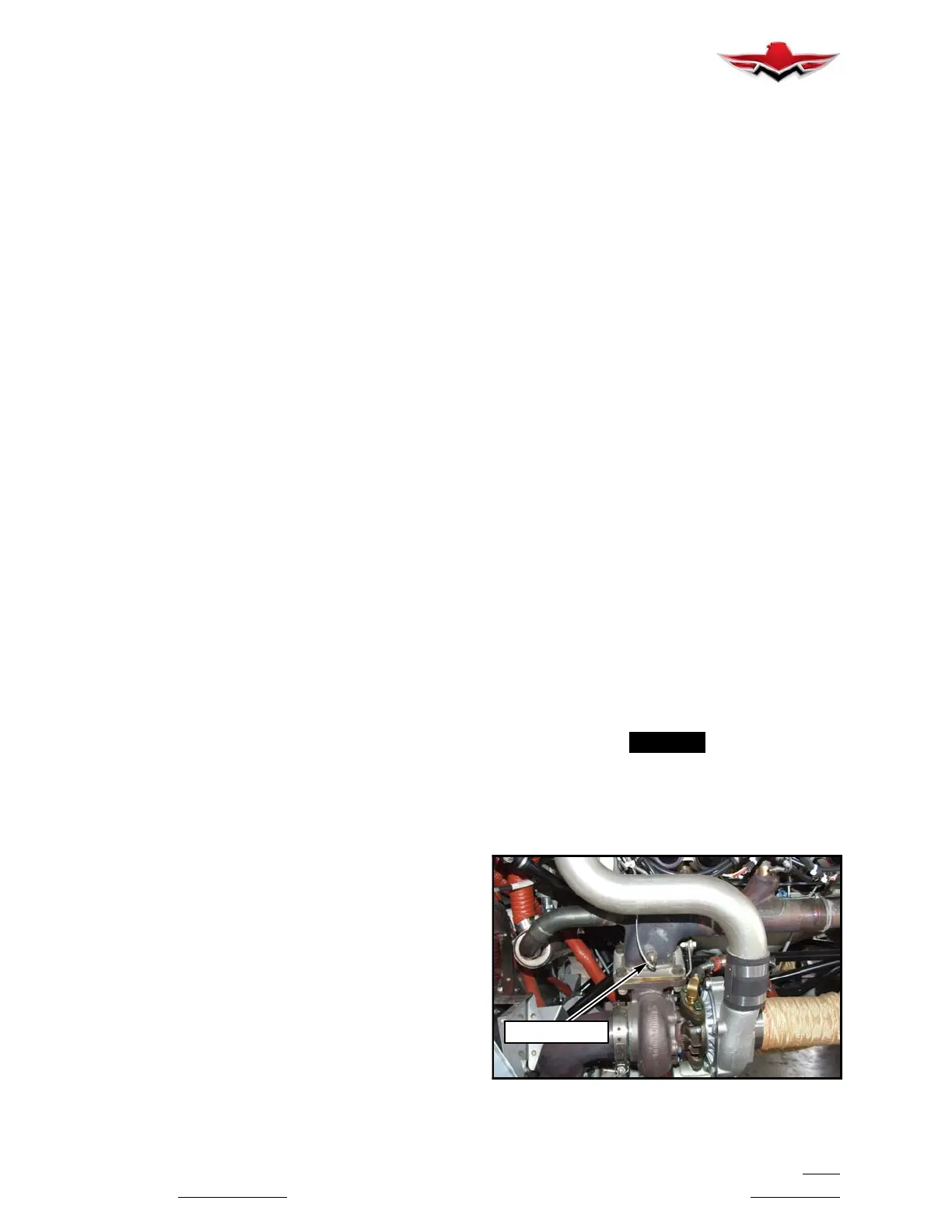
The TIT probe is installed at the inlet to the turbo-
charger on engine right hand side (Co-Pilot).
The TIT (Turbine Inlet Temperature) indicator displays
the temperature at the turbine inlets in degrees Fahren-
heit.
A. Green - Normal - 1000F to 1750F
B.Red- Warning- 1750F+
-NOTE-
The TIT gauge and sensing probe should be re-
moved and inspected for proper calibration at the
recommended 50 Hour Inspections.
The TIT probe should be re- installed and torqued
properly in accordance with the manufacturer of probe.
TIT PROBE
TIT INSTALLATION (TYP)
FIGURE 77- 1
77-00-00


 To Next Page
 Loading...