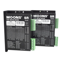
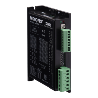
The SR4/SR8 is a 2-phase stepping motor drive designed for motion control applications. It is a cost-effective, high-performance drive based on AC servo drive technology, offering high torque, low noise, and low vibration. The drive allows users to select running current and microstep resolution via a piano switch, aiming to provide better performance for low-cost and high-quality markets.
Function Description
The SR4/SR8 drive controls 2-phase stepping motors by converting pulse and direction signals into motor movements. It features advanced digital current control for excellent high-speed torque. The drive supports various motor types, with a pre-loaded motor database accessible via a 16-bit rotary switch. This switch allows for selection of the desired motor and automatically configures parameters, including settings optimized for anti-resonance and load inertia (low or high).
Important Technical Specifications
- Power Supply:
- SR4: 24 to 48 VDC
- SR8: 24 to 75 VDC
- Output Current (Peak):
- SR4: Max 4.5 Amps Peak
- SR8: Max 7.8 Amps Peak
- Input Signal Average Forward Current: 6 to 15 mA (typical 10 mA)
- Step Frequency: Up to 2 MHz
- "STEP" Minimum Pulse Width Hi and Low: 250 ns
- "DIR" Minimum Pulse Width: 50 us
- Input Signal Voltage: 4.0 to 28 VDC
- "OUT" Maximum Output Current: 100 mA
- "OUT" Maximum Output Voltage: 30 V
- Driver Initialization Time: 2.5 S
- Microstep Resolution: Position switch selectable, 8 settings: 400, 800, 1600, 3200, 6400, 12800, 25600, 51200 step/rev.
- Speed Range: Up to 3000 rpm
- Control Modes: Step & Direction
- Input Digital Filters: 2 MHz Digital Filter for high-speed inputs
- Ambient Operating Temperature: 0-40°C [32-104°F]
- Maximum Ambient Humidity: 90% RH (No dew or bead)
- Storage Temperature: -10-70°C [14-158°F]
Usage Features
- Connecting to Power Supply: A fast-acting fuse (never exceeding 10 Amps) should be installed in series on the positive power supply lead if the power supply lacks output fusing or current limiting. Connect the motor power supply "+" terminal to "V+" and "-" to "V-". Reversing wires should be avoided.
- Connecting to Motor: The manual provides diagrams for connecting 4-lead bipolar, 6-lead series connected, 6-lead center tap connected, 8-lead parallel connected, and 8-lead series connected motors.
- Connecting to Inputs:
- Pulse & Direction Inputs: The drive has two high-speed optically isolated inputs (STEP and DIR) that accept 5 to 24 Volts single-ended or differential signals up to 2MHz (max 28V). A falling edge of the STEP signal executes one step. The DIR signal level controls rotation: low (0 level) for clockwise, high (1 level) for counterclockwise.
- EN Input: An optically isolated input (5 to 24 Volts single-ended or differential, max 28V) enables or disables the drive amplifier. When EN is closed, the amplifier is deactivated, MOSFETs shut down, and the motor is free. When EN is open, the drive is activated. A falling signal into EN resets error status and reactivates the amplifier after a fault is removed.
- Connecting Circuit: Diagrams illustrate connecting to control with sinking, sourcing, and differential outputs.
- Switch Selecting:
- Running Current: Set via SW1, SW2, and SW3 with 8 available settings to meet specific needs.
- Idle Current: The drive automatically reduces motor running current by 50% when the motor is not moving. This feature can be disabled to maintain 90% running current for high holding torque, though enabling it is recommended to minimize heating.
- Microstepping: Resolution is set via SW5, SW6, and SW7 with 8 available settings.
- Self Test: Setting SW8 to "ON" after power-up initiates a self-test, performing a 2-revolution CW/CCW move at 1 revolution per second.
- Motor Select: A 16-bit rotary switch selects different motors from a pre-loaded database, automatically configuring drive parameters. The switch also allows selecting low (1:1) or high (10:1) load inertia settings, which optimize anti-resonance. Recycling drive power is required after changing motor selection.
- Recommended Motors: The manual provides detailed specifications and torque curves for various MOONS' motor series, including 11HS, 14HY, 17HD, 23HS, and 34HD.
Maintenance Features
- Fault Output: The FAULT output is optically isolated (Max collector current 100mA, Max Collector to Emitter voltage 30V). It is open when the driver works normally and closed when an error occurs.
- Error Code (Status LED): Two LEDs (red/green) indicate status. A solid green LED indicates motor disabled. Flashing green indicates motor enabled. Red flashes combined with green flashes indicate specific errors:
- 3 red, 2 green: Internal Voltage Bad
- 4 red, 1 green: Over Voltage
- 4 red, 2 green: Under Voltage
- 5 red, 1 green: Over current/Short circuit
- 6 red, 1 green: Open motor winding
- Drive Mounting: The drive can be mounted on the wide or narrow side of a chassis using M3 screws. For continuous operation at maximum power, compulsory air-cooling is recommended due to heat generation. The drive should not be placed in spaces with no airflow, where ambient temperature exceeds 40°C, or where it might get wet or exposed to metal particles.