The Interface Solution Experts 11
FDY
PC-Programmable Frequency
Transmitter and Display
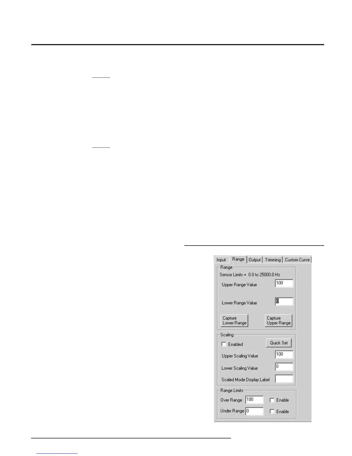
Programming the Range Parameters
The Range tab permits you to set or capture the
acceptable input range and establish range limits.
• Use the Lower Range Value cell to set the input
value that will correspond to a 4mA output. In the
same way, use the Upper Range Value to set the
input value that corresponds to a 20mA output.
• Reverse the output (causing the output to increase
as the input decreases) by setting the Lower
Range Value higher than the Upper Range Value.
• The Capture Lower Range and Capture Upper
Range buttons permit you to trim the upper and
lower range of the sensor (if necessary). Just click
the appropriate button to begin trimming.
Figure 8. Range Parameters Tab
NOTE:
If the Lower Range Value is set to 0Hz in the Input
Range the Fail On Input Time-out feature will not be
available, the Lower Range Value must be set to a
value greater than zero to enable this feature (box
must be checked to apply feature) .
Low Pass Filter Enable: Reduces noise by fi ltering out
high frequency signals.
NOTE:
Moore Industries recommends having the Low-Pass
fi lter turned on when the upper input range value is
less than 150Hz (especially on the 10VAC - 250VAC
units).
Averaging Filter: Shows the number of readings
the FDY averages together to provide the displayed
reading. This can be used to compensate for bent
blades in a monitored turbine by setting the value to
equal the number of blades on the turbine. (i.e. if the
turbine has four blades, set the Averaging Filter to 4).
Minimum Debounce Period: Available only when
contact closure is selected in measurement mode.
This value eliminates noise from a contact closure
input, but lowers the maximum measurable frequency.
After selecting the input parameters, continue
by clicking the Range tab and proceeding to the
Programming the Range Parameters section.
You are given the option of scaling your process
variable reading. To do this, click the Enabled check
box in the Scaling section. Scaling allows you to take
your process variable and manipulate the reading to a
more customized range.
• In the Upper Scaling Value text box, enter the
value you wish displayed when your input is at its
full range. Repeat the step for the value you wish
displayed when your input is at its zero value and
enter that into the Lower Scaling Value box.
At the Scaled Mode Display Label box, enter the
specifi c EGU (Engineering Unit) that you want as your
display.
• The Range Limits section allows you to designate
when the input will be considered bad (over or
under range). For example, if you have set the
Lower Range Value for 20, you can set the Under
Range for 10 and check the Enable box, allowing
the input to decrease below 10Hz before an error
is registered. In this case, the display shows
Under/Over range, and the output is in Failure
Mode (see Programming Output Parameters).