The Interface Solution Experts 13
FDY
PC-Programmable Frequency
Transmitter and Display
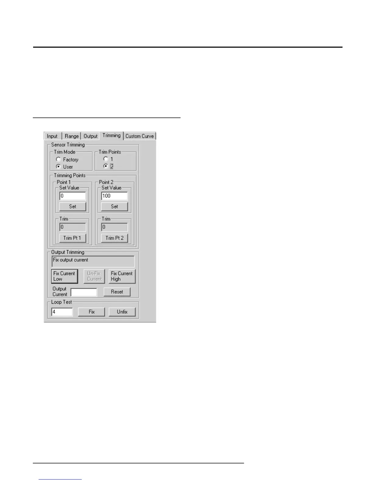
Figure 10. Trimming Parameters Tab
Programming the Trimming
Parameters
The Trimming tab includes Sensor (Input) Trimming,
Output Trimming and Loop Test functions.
Sensor Trimming
Sensor Trimming increases the measured accuracy of
your transmitter by matching the reading of its actual
input to either a calibrated source or the master device
to which it is transmitting. This causes the FDY’s
process variable and output to match its input.
Most transmitters can only trim at the 0% and 100%
points of the scale, but the FDY can trim any point
along the scale. Note that one-point trimming applies
an offset to the sensor reading, while two-point
trimming applies both an offset and gain.
Before you attempt to trim the FDY, ensure that the
correct sensor is attached to the transmitter, then go to
the Trimming tab as shown at the left, and:
1. Select the User radio button under Trim Mode, then
answer Ye s to the “Please confi rm that you want to do
this” prompt.
2. Select one or two trim points by clicking the
appropriate button under Trim Points.
3. Enter the value you want to trim into the Set Value
box under Point 1 and click Set. Apply the value you
entered in the Set Value section to the FDY. Click on
the Trim Pt 1 button. This matches the signal from the
sensor to the fi rst point you selected.
4. If you selected two trim points, enter the second
value that you want to trim into the Set Value box
under Point 2 and click Set. Then apply the value you
entered in the Point 2 box to the FDY. Click on the Trim
Pt 2 button. This matches the signal from the sensor to
the second point you selected.
5. You have now fi nished trimming your sensor and can
continue on to Output Trimming.