FDY
12 The Interface Solution Experts
PC-Programmable Frequency
Transmitter and Display
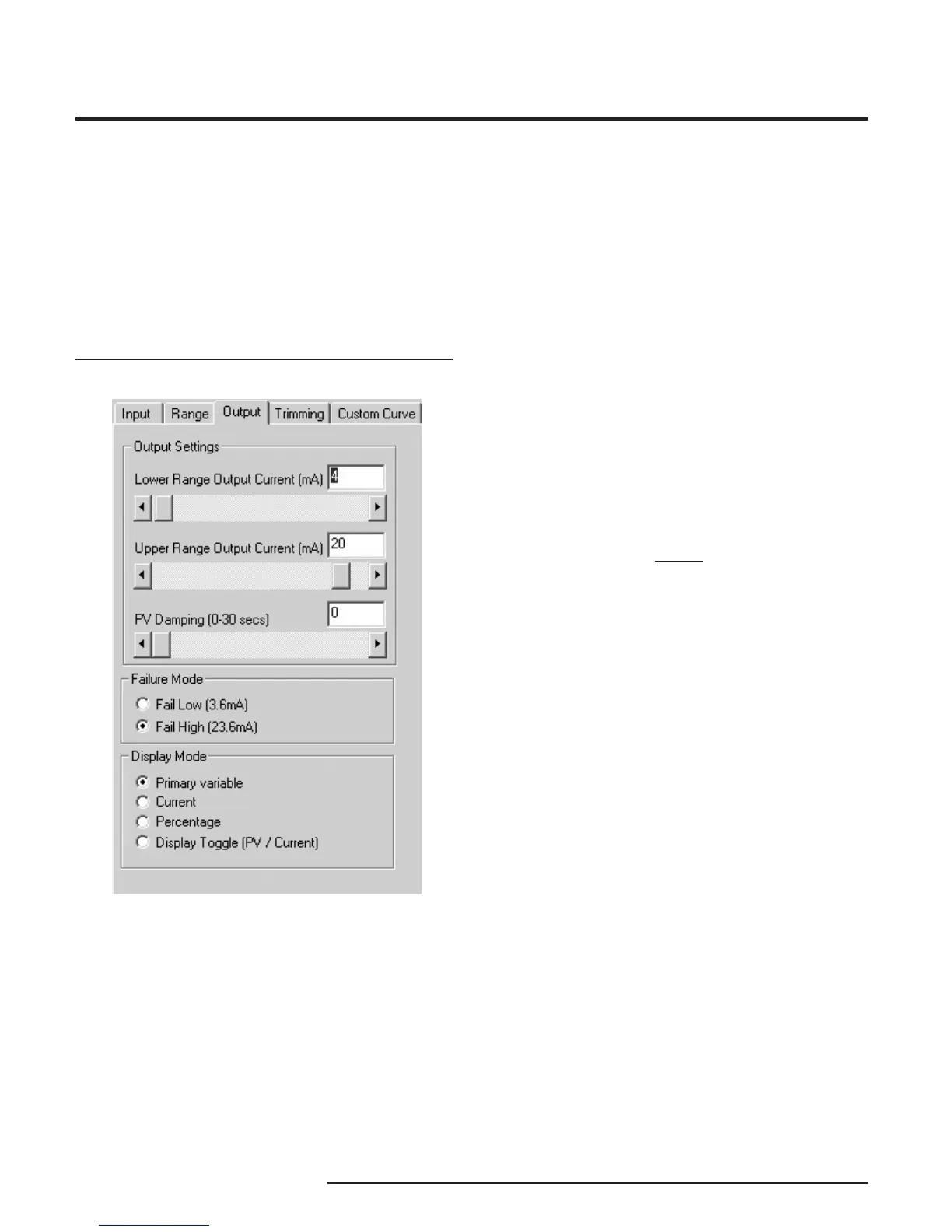
Figure 9. Output Parameters Tab
Programming the Output
Parameters
The Output section of the PC software is composed
of three sections: Output Settings, Failure Mode and
Display Mode. Use the functions of Output Settings to
set the current range from 3.8 to 21.6mA (usually
4-20mA). The minimum span is 4mA.
Output Settings
The output can be reversed (causing the output to
increase as the input decreases) by setting the Lower
Range Value in the Range tab as higher than the
Upper Range Value (See Figure 8).
PV (Primary Variable) Damping precisely reads the
input then specifi es an exponential change in the
output by 60% over the time set in the PV Damping
box. This reduces the effect of sudden spikes and
helps stop unnecessary alarms by smoothing the
reading.
Failure Mode
Failure Mode lets you set the output of the transmitter
when it is malfunctioning. It will either transmit a 3.6mA
(set to Fail Low) or a 23.6mA (set to Fail High) signal.
NOTE:
The Failure Mode has no effect unless one of the fail
conditions is active (i.e. Fail On Input Time-out or Over/
Under Range Limits).
Display Mode
Display Mode selects which variable will be displayed
on the transmitter’s display. Choose between Primary
Variable, Current, Percentage and Display Toggle.
(Display Toggle switches back and forth from the
primary variable to current and back in one-second
increments). The PC Program’s display is not changed
by changing the selection under the Display Mode.
After the Range parameters have been selected, you
can continue on by clicking on the Trimming tab, and
proceeding to Programming the Trimming Parameters.