Do you have a question about the Morco II Series and is the answer not in the manual?
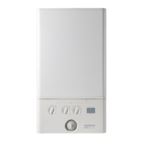
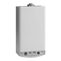
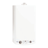
Overview of the Morco GB Series II boilers: fanned flue, high efficiency, condensing gas boilers.
Describes how the boiler operates for central heating and domestic hot water demands.
Precautions and guidelines for safely moving and installing the boiler unit.
Lists and describes optional accessory kits for flue installation and extensions.
Covers gas safety, electrical safety, and regulatory compliance for installation and use.
Information regarding the absence of hazardous substances like asbestos, mercury, or CFCs.
Details boiler dimensions, required clearances for installation, and service access.
An exploded view illustrating the boiler components with numbered references.
Guidance on calculating and installing the correct flue length for safe operation.
Provides diagrams and formulas for calculating flue length for rear and side installations.
Step-by-step instructions for cutting the horizontal flue terminal to the correct size.
Detailed instructions for fitting the flue through the wall and securing the turret assembly.
Instructions for assembling and installing optional flue extension kits.
Details on fitting the flue deflector kit for horizontal deflection of flue products.
Information on using the 90° elbow kit for flue installations, including length calculations.
Instructions for fitting the optional roof flue kit, including weatherproofing.
Steps for assembling the roof flue kit, including the vertical connector and clamp.
Details on the condensate trap system, pipework requirements, and drainage connection methods.
Schematic diagram showing the boiler's electrical connections and components.
Provides a schedule for routine servicing and maintenance of the boiler.
Key checks to perform during routine servicing or after component changes.
Specifies requirements for personnel performing combustion analysis.
Instructions on how to access and use the boiler's service mode for diagnostics.
Step-by-step guide for removing and refitting the boiler's front panels.
Procedure for removing, cleaning, and inspecting the fan and venturi assembly.
Instructions for safely removing and cleaning the boiler's burner assembly.
Procedure for draining and cleaning the condensate trap or siphon.
Steps for thoroughly flushing and cleaning the boiler's heat exchanger.
Guidance on reassembling the boiler components after servicing or replacement.
General precautions and steps before replacing any boiler component.
Detailed procedure for replacing the boiler's fan assembly.
Instructions for replacing the burner injector unit.
Procedure for removing and replacing the main burner assembly.
Steps for safely removing and replacing the ignition electrode.
Procedure for removing and replacing the flame detection electrode.
Instructions for replacing the spark generator unit.
Procedure for safely removing and replacing the gas control valve.
Steps for removing and replacing the diverter valve actuator motor.
Procedure for replacing the boiler's condensate trap or siphon.
Instructions for replacing the main printed circuit board (PCB) and boiler chip card.
Procedure for replacing the user control printed circuit board (PCB).
Steps for removing and replacing the mechanical timer unit.
Detailed procedures for draining the central heating and domestic hot water circuits.
Instructions for replacing the domestic hot water flow turbine sensor.
Procedure for replacing the boiler's pressure gauge.
Steps for removing and replacing the safety relief valve.
Procedure for replacing the automatic air vent on the pump.
Instructions for removing and replacing the diverter valve body assembly.
Procedure for replacing the domestic hot water plate heat exchanger.
Steps for removing and replacing the boiler's pump head.
Procedure for replacing the central heating water pressure switch.
Instructions for cleaning or replacing the DHW filter and flow regulator.
Procedure for removing and replacing the flow thermistor.
Steps for removing and replacing the return thermistor.
Procedure for removing and replacing the heat engine assembly.
Instructions for recharging or replacing the expansion vessel.
Procedure for replacing the boiler's front panel sealing strip.
Explains the different display codes and their corresponding boiler operating modes.
Lists common fault codes, their descriptions, and recommended actions.
Troubleshooting guide for flow temperature overheat lockout faults.
Troubleshooting guide for ignition lockout faults.
Troubleshooting guide for boilers resetting five times within 15 minutes.
Troubleshooting guide for false flame lockout faults.
Troubleshooting guide for low water pressure issues.
Troubleshooting guide for flame loss faults.
Troubleshooting guide for fan faults.
Troubleshooting guide for flow thermistor faults, including resistance checks.
Troubleshooting guide for return thermistor faults, including resistance checks.
Troubleshooting guide for low mains voltage issues.
Troubleshooting guide for main PCB faults, including checking the Boiler Chip Card (BCC).
Troubleshooting guide for BCC activation faults.
Troubleshooting guide for BCC faults, focusing on correct insertion and replacement.
Troubleshooting guide for scenarios where central heating is not working but hot water is.
Troubleshooting guide for scenarios where hot water is not working but central heating is.
Troubleshooting guide for when the boiler display shows no information.
| Ignition | Electronic |
|---|---|
| Model | II Series |
| Fuel Type | LPG |
| Gas pressure (mbar) | 37 |
| Safety Features | Flame failure device, overheat thermostat |