Page 20
CREASING
SECTION 9
ELECTRICS: REMOVAL/REFITTING PCB/POWER SUPPLY ASSEMBLY
REPLACEMENT OF MAIN CONTROL P.C.B.
All the Electric controls and pcbs are located within the rear cover mounted on a common
base plate.
This PCB controls all functions of the machine and houses the Main Program PCB.
The use of an antistatic wrist band should be used during work on the main control PCB.
Switch the mains power off and disconnect from the mains supply.
Unplug all the green plugs from the PCB.
Using a posi-drive screw driver, unscrew the five fixing screws and carefully remove the PCB.
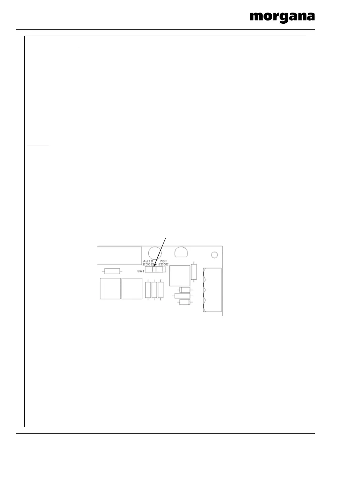
When fitting a new board it is important that the switch, , must be set in the correct
position. For machines with Serial No. 730419 or higher the switch must be set over to the left
in the position; these machines were fitted with as
standard. For machines with Serial numbers earlier than 730419 the switch must generally be
set over to the right in the position, unless the machine has been upgraded to
include Earlier Machines that have been upgraded with
will have a main processor revision of A1.3x1 or higher and a
touchscreen software revision of AC5.0x3 or higher; for these machines the switch must be set
over to the left in the position. See technical bulletin TB2744 Iss.B. for further
information.
SWITCH (SW1)
SW1
AUTO EDGE Lead Edge Auto Sensing
POT EDGE
Lead Edge Auto Sensing. Lead
Edge Auto Sensing
AUTO EDGE
NOTE.