MACHINE PREPARATION and OPERATION (Cont.)
LASER SIGHT GUIDE SYSTEM
1 The laser sight system is intended as a guide only
and should not be used for accuracy of the cut.
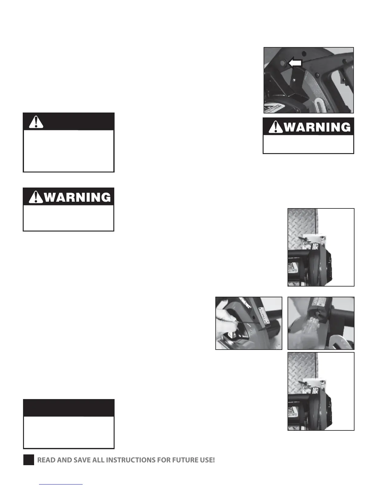
2 Depress Laser power switch (Fig. 6)
3 Laser Beam follows the angle of the base plate.
4 Alight laser beam with your cut line.
5 After completing the cut depress the laser power
switch to disconnect power to laser.
ALIGNMENT TIPS FOR LASER SIGHT GUIDE
1 Find a square, at work piece of either steel or plywood
and place the work piece on a table. (Fig. 7)
2 Push the blade guard up and away from the blade.
3 Place the saw on the top of the work piece.
The blade should touch the edge of the work piece. (Fig. 7)
ADJUSTING FOR PARALLEL
Depress power laser power switch. If the laser line does not
line up with the edge of work piece then:
a. For small adjustments use a M2 hex key and loosen
or tighten the screw adjustment. (Fig. 8) to bring
the beam back to parallel.
b. For larger adjustments use a small at head screw
driver to the slot in the front of the light (Fig. 9)
to realign the beam. Then use the M2 hex key and
loosen or tighten the screw in order to do the nal
positioning. (Fig. 10)
c. The laser light and the 2 sight line markings, on the
base plate should now be in the same plane.
5
LASER RADIATION
Avoid direct eye contact
with light source.
Do not point laser at anyone.
Never look into the laser light.
Turning the laser o does not turn
power o to the saw.
READ AND SAVE ALL INSTRUCTIONS FOR FUTURE USE!
DANGER
Do not turn on saw
for this adjustment!
Serious injury could result.
Do not overturn the adjustment
screw on the front of the light.
You could damage threads or the
plastic housing for the laser.
CAUTION
(FIG. 6)
(FIG. 8)
(FIG. 9)
(FIG. 10)
(FIG. 7)