Ø127
Ø108
1
2
2
2
2
4
3
5
6
7
Revisions
Rev.
Sign.:
Title:
Drawing no.:
1:10
Monteringsvejledning airtight
5660
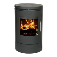
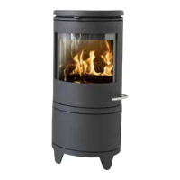
Morsø 5600
RSV
31.10.06
A3
Exploded Diagram
127,21 kg
ERROR!:materiale
Date of print: 25-08-2010
U:\udv\Tegninger\5600\5600 Assembly.SLDASM
5600-102 b
Itemno.:
This drawing is Morsø Jernstøberi A/S' property and must not be sold, lended or copied without any written authorization from the company.
Material:
Weight:
Model no.
Drawingtype:
Location of file:
Scale:
Format:
Released:
Construction:
Date:
b Påført glastape. RSV 25.08.2010
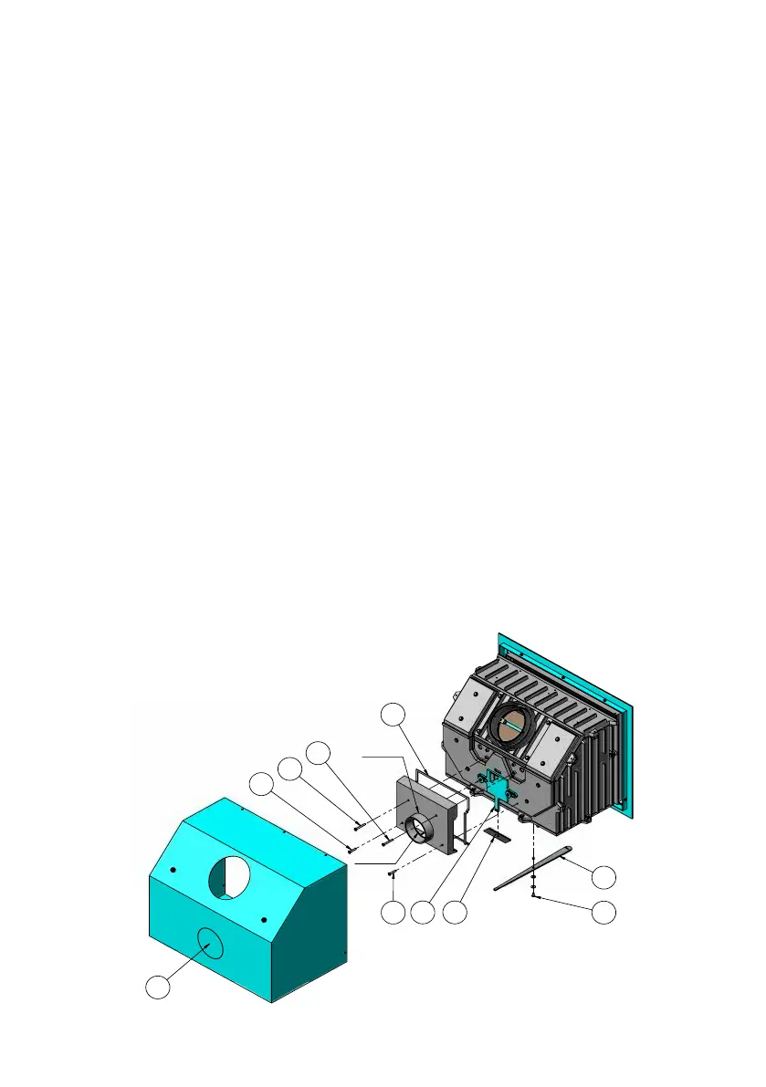
Installation Instructions
Morsø 5660 Outside Air Kit
The kit consists of:
1 pcs. Outside Air Box
1 pcs. cover plate
2 pcs. screws 6x35 mm
2 pcs. screws 6x55 mm
110 cm tape
1. Before tting the air kit set knock out the steel plate (1) in the insert box. This is best
done by applying gentle hammer taps immediately onto the small ”bridges” in the circu-
lar cutouts.
2. Remove cast combustion chamber from the convection box and unscrew the control bar (4)
from the cast iron base fastened with the screw (5) in the middle. Now place the cover plate
(3) around the air slide tted (6) at the back of the stove (see drawing). Ret the control bar
(4) on the cast iron base plate.
3. The 4 M6x8 screws tted at the back of the cast iron plate, where the air kit box is to be
fastened, are removed.
4. Paste the tape (7) to the edge all around the air kit box.
5. Remove the 4 M6x8 (2) screws located at the back of the cast iron plate where the air
kit box is to be tted. Make sure that the cover plate (3) is tted correctly inside at the
bottom of the box. (see drawing).
The stove can be installed. See the enclosed Instructions for installation and use.